T-Wizard CommandDifficultyadvancedAdded2027.0StatusdraftT-Intersection Wizard Command
Description:
Creates a T-intersection between two corridors automatically. If you have a cross intersection, you can design it as two T-intersections. The created intersection can be modified manually, or it can be recreated when the road's geometry changes.
Location on Compact Ribbon:
Location on Extended Ribbon:
Create T-Intersection
The following objects must be in the drawing before the Intersection Wizard is used:
-
Main road and secondary road corridors (the secondary road vertical alignment does not need to be tied in with the main road vertical alignment, the intersection wizard will adjust the secondary road's vertical alignment automatically, it will add a PVI at the point where the secondary road vertical alignment crosses the main road edge – ETW, however it is always better to tie the secondary road's vertical alignment to the main road)
-
Assemblies for main road at intersection and right and left curb return. The image below shows two assemblies for the main road at the intersection but only one assembly is needed if all the intersections are on one secondary of the main road:

The Null assembly is an empty assembly (it is used for the secondary road at the area where it crosses the main road):

-
Curb returns drawn with polylines:
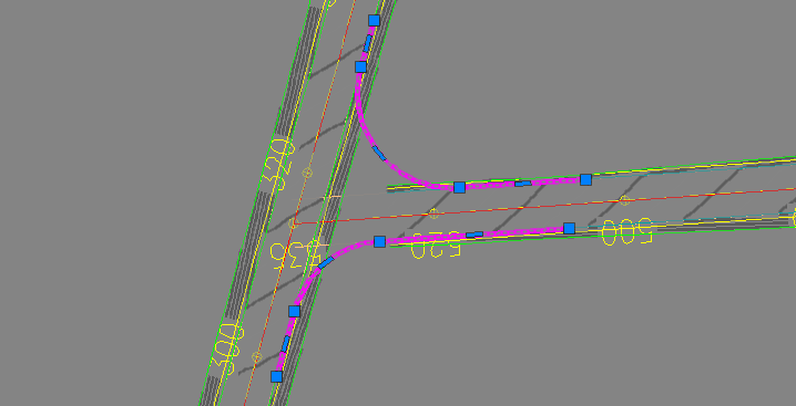
Polylines must be drawn exactly on the roads' ETW feature lines. Devotech iDAS uses feature line levels at the curve and tangents start and end to design the curb return vertical alignment. It is important that the secondary road corridor is not too short, so the curb return curve start or end is on the corridor feature line:
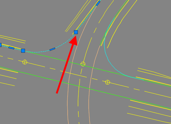
You can draw the polylines manually Curb Returns Command.
-
To create an intersection, run the command and select the point where the two horizontal alignments cross each other:
-
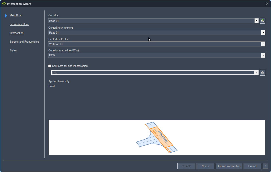
Select the main road as shown in the image of the Intersection Wizard and set the properties.
-
Select the secondary road as shown in the image of the Intersection Wizard and set the properties.
Corridor Top Surface: this setting can be ignored as it is used for medians which are not fully implemented yet.
Assembly over Main Road Section: this assembly is applied for the secondary road across the main road. Created region should be switched off or deleted manually for cross intersections otherwise feature lines from corridors will stop at the first intersection.
-
Set the curb return polylines and subassemblies. The curb return left and right secondary is defined from the driver's point of view when driving on the secondary road and approaching the main road. A secondary road chainage direction is irrelevant:
-
Specify the Target Surface and Frequencies:
-
Specify the styles and click on the Create Intersection button:
-
The contours of the created intersection might not display correctly. Use the Regen command to update them.
Final intersection before Regen command was used:
Final intersection after Regen command was used:
If the Regen command does not fix the contours, which might happen when designing a cross intersection, rebuild the secondary road corridor manually.
The Intersection Wizard creates two new sites. One site for the main road corridor feature line and another site for the curb return horizontal alignments. Two sites are used because the feature lines and alignments are interactive if they are in the same site.
If the T-Intersection Wizard fails, the two created sites might remain in the Prospector. If it does happen, delete these sites to keep the drawing clean.
T-Intersection Wizard Report
Devotech iDAS T-Intersection Wizard provides detailed progress during the intersection creation. If all the operations are successful, then the following details are provided in the command line:
Finding the closest intersection point.....................................................successful.
Determining Secondary Road's direction.....................................................successful.
Extracting Main Road's feature line, alignment and profile.................................successful.
Finding intersection point between Secondary Road's alignment and Main Road's feature line.successful.
Adjusting Secondary Road's centerline profile..............................................successful.
Updating Secondary Road's centerline profile's elevation...................................successful.
Rebuilding the roads.......................................................................successful.
Extracting Secondary Road's feature line, alignment and profile............................successful.
Converting the left polyline to an alignment...............................................successful.
Determining intersection point of left alignment with Secondary Road's feature line........successful.
Determining intersection point of left alignment with Main Road's feature line.............successful.
Creating the left curb return profile......................................................successful.
Adding start VPI to left curb return profile...............................................successful.
Adding start and end of curb return VPIs to left curb return profile.......................successful.
Adding end VPI to left curb return profile.................................................successful.
Adding left alignment to Secondary Road as a baseline......................................successful.
Setting the targets of the left curb return region.........................................successful.
Converting the right polyline to an alignment..............................................successful.
Determining intersection point of right alignment with Secondary Road's feature line.......successful.
Determining intersection point of right alignment with Main Road's feature line............successful.
Creating the right curb return profile.....................................................successful.
Adding start VPI to right curb return profile..............................................successful.
Adding start and end of curb return VPIs to right curb return profile......................successful.
Adding end VPI to right curb return profile................................................successful.
Adding right alignment to Secondary Road as a baseline.....................................successful.
Setting the targets of the right curb return region........................................successful.
Shortening Secondary Road..................................................................successful.
Setting the frequency of the right curb return region......................................successful.
Setting the frequency of the left curb return region.......................................successful.
Updating surface target of Main Road.......................................................successful.
Updating surface target of Main Road.......................................................successful.
Updating surface target of Main Road.......................................................successful.
Updating surface target of Main Road.......................................................successful.
Updating surface target of Main Road.......................................................successful.
Updating surface target of Main Road.......................................................successful.
Updating surface target of Main Road.......................................................successful.
Splitting Main Road........................................................................successful.
Intersection design complete. May require a REGEN.
If the list is not complete or if there is a failed operation then the T-Intersection Wizard failed to create the intersection. The last row will give an indication of why an error occurred if there was one, otherwise it will say Intersection design complete. May require a REGEN. Make sure to REGEN the drawing once the intersection is complete.
Corridor's Regions Adjustments
If T-Intersection Wizard finishes the intersection design successfully but the intersection does not look right, then adjust corridor regions accordingly (see the south west intersection in the image below):
Before:
After:
Issues Causing T-Intersection Wizard to Fail
If any of the following scenarios are present in the drawing, then the T-Intersection Wizard will fail to create an intersection:
Incorrectly drawn curb return polyline
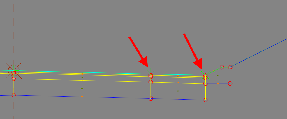
Curb return polylines are not overlapping the corridor feature lines exactly:
Long curb return polylines
Curb return polylines extend beyond the secondary road corridor:
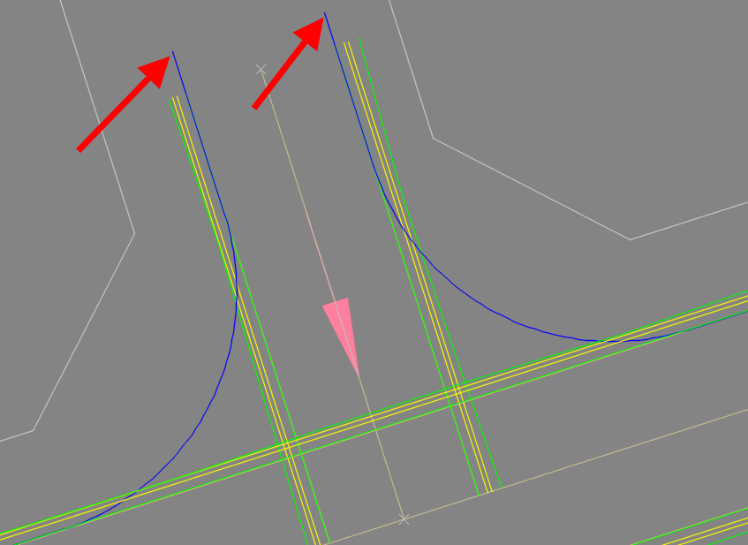
Short secondary road corridor
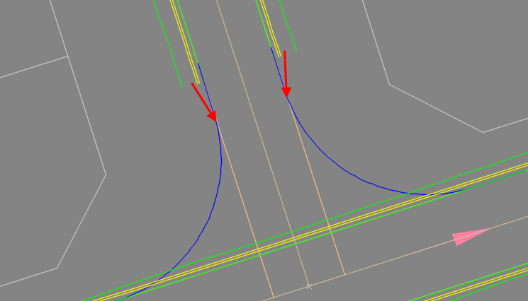
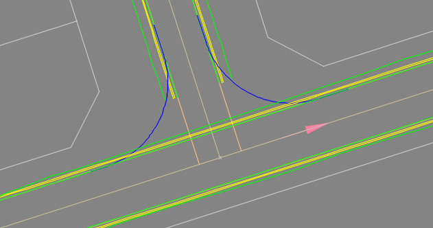
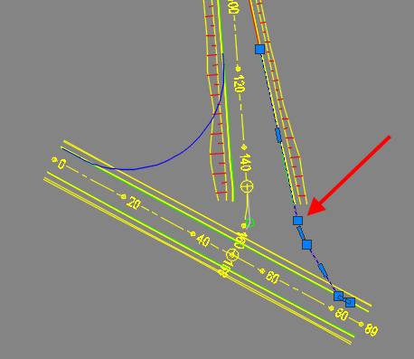
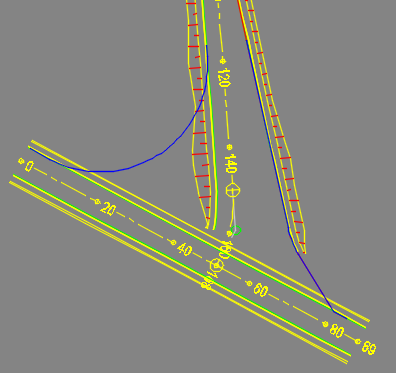
BCC and ECC of the polyline curve must touch the corridor feature lines (road corridors must not stop before the curb return curve starts).
EXAMPLE 1
Incorrect ─ secondary road corridor is too short:
Correct ─ corridor was stretched beyond the curb return curve start/end:
EXAMPLE 2
Incorrect ─ secondary road corridor is too short:
Correct ─ corridor was stretched beyond the curb return curve start/end:
Short one curb return polyline
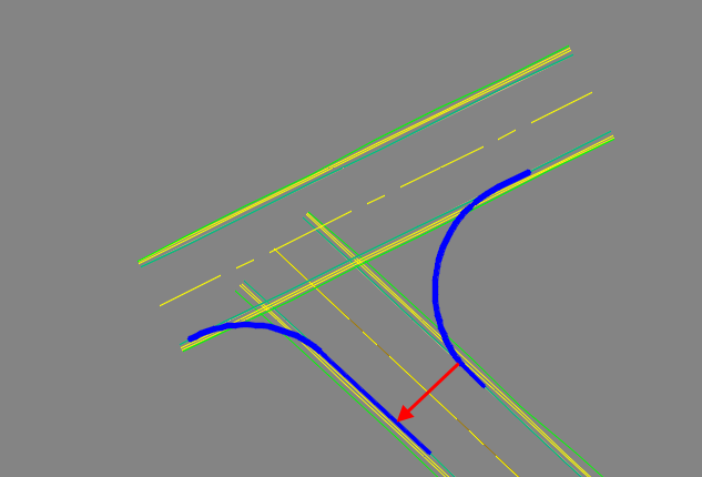
One curb return polyline ends before the point where the other curb return polyline connects to the road edge:
Incorrect ─ left curb return polyline is too short: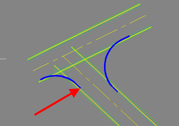
Correct ─ left curb return polyline extends beyond the point where right curb return polyline connects to the edge of the road:
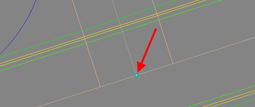
Short secondary road centerline
Secondary road horizontal alignment must be snapped to the main road horizontal alignment, or it must cross it:
Split regions at intersection area
Main road or secondary road corridor has a split region at the intersection area.
Incorrect code for road edge (ETW)
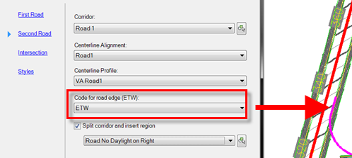
Code for road edge in the Intersection Wizard does not correspond with the feature line that the polyline was drawn on:
Multiple points with the same code
Assembly has multiple points with the Code for road edge used in the Intersection Wizard. The assembly shown below has two points with the ETW code on the right-hand secondary which can cause the problem:
Loop road (correct workflow must be used)
If you need to design an intersection for the loop road (the road intersects itself), then you must use a specific workflow, watch this video for details:
Error message
If the message below appears on the screen, then close Civil 3D and reopen it:
Error Messages Provided by T-Intersection Wizard
Determining intersection point of left alignment with Road 2's feature line
Example 1:
Finding the closest intersection point..........................................successful.
Determining Road 1's direction..................................................successful.
Extracting Road 2's feature line, alignment and profile.........................successful.
Finding intersection point between alignment 1 and Road 2's feature line........successful.
Adjusting Road 1 centerline profile.............................................successful.
Updating Road 1 centerline profile's elevation..................................successful.
Rebuilding the roads............................................................successful.
Extracting Road 1's feature line, alignment and profile.........................successful.
Converting the left polyline to an alignment....................................successful.
Determining intersection point of left alignment with Road 1's feature line.....successful.
Determining intersection point of left alignment with Road 2's feature line.....
Intersection design complete. May require a REGEN.
Command: Specify opposite corner or [Fence/WPolygon/CP
Example 2:
Finding the closest intersection point..........................................successful.
Determining Road 1's direction..................................................successful.
Extracting Road 2's feature line, alignment and profile.........................successful.
Finding intersection point between alignment 1 and Road 2's feature line........successful.
Adjusting Road 1 centerline profile.............................................successful.
Updating Road 1 centerline profile's elevation..................................successful.
Rebuilding the roads............................................................successful.
Extracting Road 1's feature line, alignment and profile.........................successful.
Converting the left polyline to an alignment....................................successful.
Determining intersection point of left alignment with Road 1's feature line.....successful.
Determining intersection point of left alignment with Road 2's feature line.....successful.
Creating the left curb return profile...........................................successful.
Adding start VPI to left curb return profile....................................successful.
Adding start and end of curb return VPIs to left curb return profile................successful.
Adding end VPI to left curb return profile......................................successful.
Adding left alignment to Road 1 as a baseline...................................successful.
Setting the targets of the left curb return region..............................successful.
Converting the right polyline to an alignment...................................successful.
Determining intersection point of right alignment with Road 1's feature line....successful.
Determining intersection point of right alignment with Road 2's feature line....
Intersection design complete. May require a REGEN.
These errors are caused by an incorrectly drawn curb return polyline. In some cases, the curb return (curb return) polylines might look correct but the intersection wizard fails during the operations that deal with curb return polylines. In these cases deleting and recreating curb return polylines might solve the problem.
Adding right alignment to Road 1 as a baseline…failed
Example:
Finding intersection point between alignment 1 and Road 2's feature line..........successful.
Adjusting Road 1 centerline profile...............................................successful.
Updating Road 1 centerline profile's elevation....................................successful.
Rebuilding the roads..............................................................successful.
Extracting Road 1's feature line, alignment and profile...........................successful.
Converting the left polyline to an alignment......................................successful.
Determining intersection point of left alignment with Road 1's feature line.......successful.
Determining intersection point of left alignment with Road 2's feature line.......successful.
Creating the left curb return profile.............................................successful.
Adding start VPI to left curb return profile......................................successful.
Adding start and end of curb return VPIs to left curb return profile................successful.
Adding end VPI to left curb return profile........................................successful.
Adding left alignment to Road 1 as a baseline.....................................successful.
Setting the targets of the left curb return region................................successful.
Converting the right polyline to an alignment.....................................successful.
Determining intersection point of right alignment with Road 1's feature line......successful.
Determining intersection point of right alignment with Road 2's feature line......successful.
Creating the right curb return profile............................................successful.
Adding start VPI to right curb return profile.....................................successful.
Adding start and end of curb return VPIs to right curb return profile...............successful.
Adding end VPI to right curb return profile.......................................successful.
Adding right alignment to Road 1 as a baseline....................................failed.
Intersection design complete. May require a REGEN.
This error is caused by an incorrectly drawn curb return polyline. In some cases, the curb return polylines might look correct but the intersection wizard fails during the operations that deal with curb return polylines. In these cases deleting and recreating curb return polylines might solve the problem.
Loop road intersection
If you are creating a loop road intersection, then you must shorten the corridor so it does not overlap with the intersection region otherwise the error above occurs. On the image below, the corridor is shorten to not to overlap with the curb return polylines at the "main road" region:
Updating surface target of Main Corridor…failed
Example 1
Below is an example of failed T-Intersection Wizard that was caused by the last region with the Null assembly in the secondary road corridor despite the fact that message shows the issue with the Main Corridor (we are aware of this discrepancy):
Finding the closest intersection point..........................................successful.
Determining Road 1's direction..................................................successful.
Extracting Road 2's feature line, alignment and profile.........................successful.
Finding intersection point between alignment 1 and Road 2's feature line........successful.
Adjusting Road 1 centerline profile.............................................successful.
Updating Road 1 centerline profile's elevation..................................successful.
Rebuilding the roads............................................................successful.
Extracting Road 1's feature line, alignment and profile.........................successful.
Converting the left polyline to an alignment....................................successful.
Determining intersection point of left alignment with Road 1's feature line.....successful.
Determining intersection point of left alignment with Road 2's feature line.....successful.
Creating the left curb return profile...........................................successful.
Adding start VPI to left curb return profile....................................successful.
Adding start and end of curb return VPIs to left curb return profile................successful.
Adding end VPI to left curb return profile......................................successful.
Adding left alignment to Road 1 as a baseline...................................successful.
Setting the targets of the left curb return region..............................successful.
Converting the right polyline to an alignment...................................successful.
Determining intersection point of right alignment with Road 1's feature line....successful.
Determining intersection point of right alignment with Road 2's feature line....successful.
Creating the right curb return profile..........................................successful.
Adding start VPI to right curb return profile...................................successful.
Adding start and end of curb return VPIs to right curb return profile...............successful.
Adding end VPI to right curb return profile.....................................successful.
Adding right alignment to Road 1 as a baseline..................................successful.
Setting the targets of the right curb return region.............................successful.
Inserting NULL region on Road 1.................................................
Updating surface target of Main Corridor........................................successful.
Updating surface target of Main Corridor........................................successful.
Updating surface target of Main Corridor........................................successful.
Updating surface target of Main Corridor........................................successful.
Updating surface target of Main Corridor........................................successful.
Updating surface target of Main Corridor........................................successful.
Updating surface target of Main Corridor........................................successful.
Updating surface target of Main Corridor........................................successful.
Updating surface target of Main Corridor........................................successful.
Updating surface target of Main Corridor.................................successful.failed.
Once the region with Null assembly was removed, the T-Intersection Wizard created the intersection successfully:
Example 2
If your main road corridor is referenced via Data Shortcuts then you should not split the main road corridor, otherwise you get the following error:
Finding the closest intersection point..........................................successful.
Determining Road 1's direction..................................................successful.
Extracting Road 2's feature line, alignment and profile.........................successful.
Finding intersection point between alignment 1 and Road 2's feature line........successful.
Adjusting Road 1 centerline profile.............................................successful.
Updating Road 1 centerline profile's elevation..................................successful.
Rebuilding the roads............................................................successful.
Extracting Road 1's feature line, alignment and profile.........................successful.
Converting the left polyline to an alignment....................................successful.
Determining intersection point of left alignment with Road 1's feature line.....successful.
Determining intersection point of left alignment with Road 2's feature line.....successful.
Creating the left curb return profile...........................................successful.
Adding start VPI to left curb return profile....................................successful.
Adding start and end of curb return VPIs to left curb return profile................successful.
Adding end VPI to left curb return profile......................................successful.
Adding left alignment to Road 1 as a baseline...................................successful.
Setting the targets of the left curb return region..............................successful.
Converting the right polyline to an alignment...................................successful.
Determining intersection point of right alignment with Road 1's feature line....successful.
Determining intersection point of right alignment with Road 2's feature line....successful.
Creating the right curb return profile..........................................successful.
Adding start VPI to right curb return profile...................................successful.
Adding start and end of curb return VPIs to right curb return profile...........successful.
Adding end VPI to right curb return profile.....................................successful.
Adding right alignment to Road 1 as a baseline..................................successful.
Setting the targets of the right curb return region.............................successful.
Inserting NULL region on Road 1.................................................
Updating surface target of Main Corridor........................................successful.
Updating surface target of Main Corridor........................................successful.
Updating surface target of Main Corridor........................................successful.
Updating surface target of Main Corridor........................................successful.
Updating surface target of Main Corridor........................................successful.
Updating surface target of Main Corridor........................................successful.
Updating surface target of Main Corridor........................................successful.
Updating surface target of Main Corridor........................................successful.
Updating surface target of Main Corridor........................................successful.
Updating surface target of Main Corridor.................................successful.failed.
How to Delete Intersection Created with T-Intersection Wizard
-
Open the Corridor Properties and delete the curb return baselines:
-
Go to the Prospector and delete the sites for the specific intersection. Each intersection has two sites, one for the curb return alignments and one for the feature lines (alignments and feature lines are interactive if they are in the same site and that will cause a problem with the feature line elevations).
The site name consist of Main Road - Secondary Road and information whether the site is for Curb Return Alignments or Feature Lines: