Wizard CommandDifficultyintermediateAdded2027.0StatusdraftCorridor Wizard Command
Description:
Creates multiple corridors from selected objects. The following objects can be used for the selection:
- Polylines
- Horizontal alignments
- Horizontal alignments in a CSV file
- Vertical alignments in a CSV file
For each object it creates:
- Horizontal alignment
- Vertical alignment
- Profile from selected NGL surface
- Profile view
- Corridor
- Corridor top surface
- Corridor datum surface
- Road edge profiles
- Sample lines (optional)
The profile view bands settings (Profile 1 and Profile 2) can also be specified in the Corridor Wizard.
Location on Compact Ribbon:
Location on Extended Ribbon:
Instructions:
The drawing must contain a surface, polylines and an assembly.
-
Run the command.
-
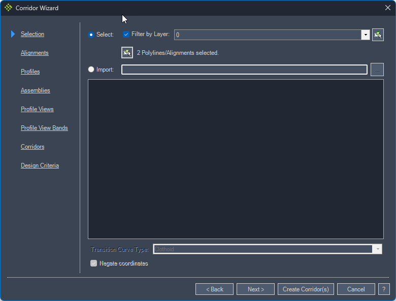
In the Selection tab choose if only the polylines/alignments from a specific layer should be processed, then click the select button to select polylines /alignments from the drawing. Alternatively, you can import a .csv file.
The .csv file must contain X and Y coordinates for points of intersection (PI). If there is a horizontal curve at the point of intersection, you can add its radius. There is also an option to add transition curves. The data in the .csv files can be organized in any order because a user can map the properties to a specific column:
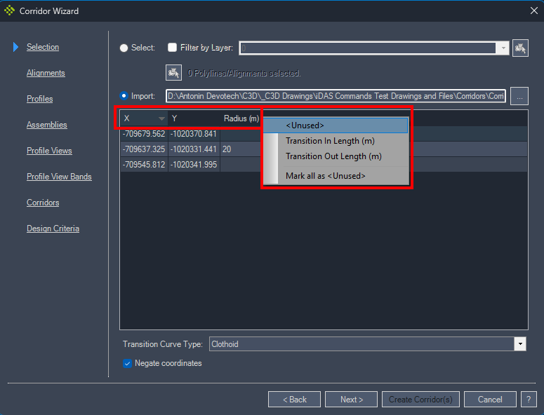
The .csv file example:

-
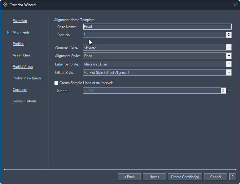
In the Alignments tab set the Alignment Name Template (the base name is used for each alignment and a number is added next to the name), Alignment Style, Label Set and Sample Lines:
-
In the Profiles tab specify the styles to use for the various profiles and the amount by which the vertical alignment should be raised or lowered.
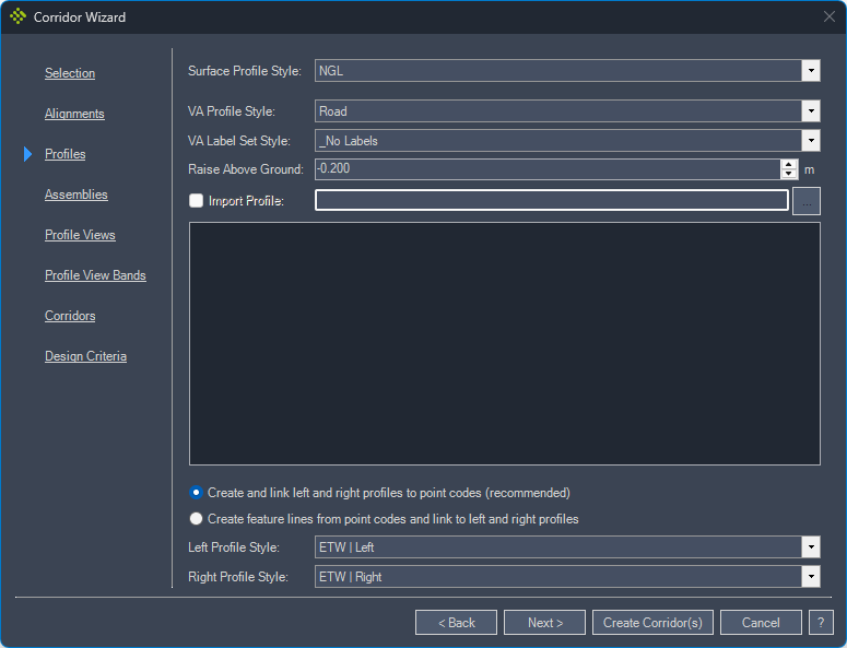
If you only selected one polyline in the Selection tab or if you imported the alignments from a file, you will be allowed to import a .csv file to create the vertical alignment profile. The .csv file must contain station and elevation for points of vertical intersection (PVI). If there is a vertical curve at the PVI, you can add its radius or length. The data in the .csv files can be organized in any order because a user can map the properties to a specific column:
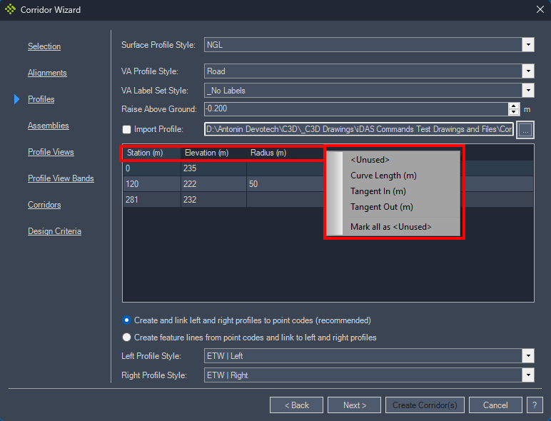
The .csv file example:

-
In the Assemblies tab choose the assembly, Lane Subassembly (it is used for the width target), Lane Elevation Point Code (this code is used for corridor feature line extraction), Corridor Feature Line Style, Target Surface and Lane Width (it overrides the default assembly width; therefore, one assembly can be used for different road classes if the layerworks are the same):
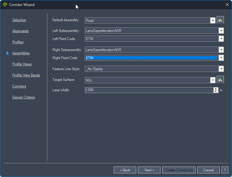
-
In the Profile Views tab choose if the profile view must be created, and set the Profile View and Profile Label Set styles:
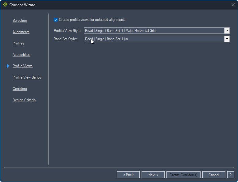
-
In the Profile View Bands tab set the profiles for Profile 1 and Profile 2:
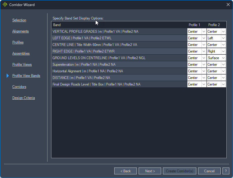
-
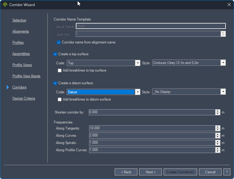
In the Corridors tab set the Corridor Name Template (the base name is used for each corridor and a number is added next to the name), Corridor Surfaces and Frequencies
-
In the Design Criteria tab choose if the superelevation must be calculated according to the NGL surface slope (the road's cross slope is opposite to the surface slope), and the Design Criteria file.

Created corridors with top surfaces:
Created profile views:
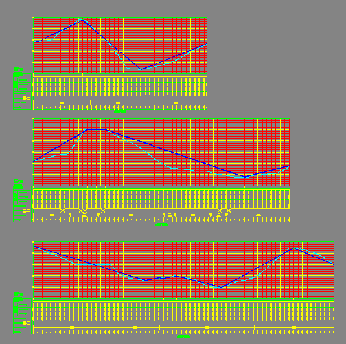
The road vertical alignments do not have vertical curves at the points of vertical intersection added automatically, the user needs to add them manually.

Road top surface contours indicating the road cross slope against the surface slope:
The corridor wizard creates offset alignments at the road edges as well as the left and right edge profiles. These profiles are linked to the auto corridor feature lines extracted from the corridor. These feature lines are added under the site named according to the corridor name: