Profile Feature Line Command
Description:
Creates a profile from a corridor feature line that is dynamically linked to a corridor (the standard Civil 3D only allows static profiles from corridor feature lines so if any changes are made to the corridor, the profiles must be recreated). If changes are made to the corridor, the profile can be updated using the Corridors − Rebuilt Feature Profiles command.
Typical applications:
-
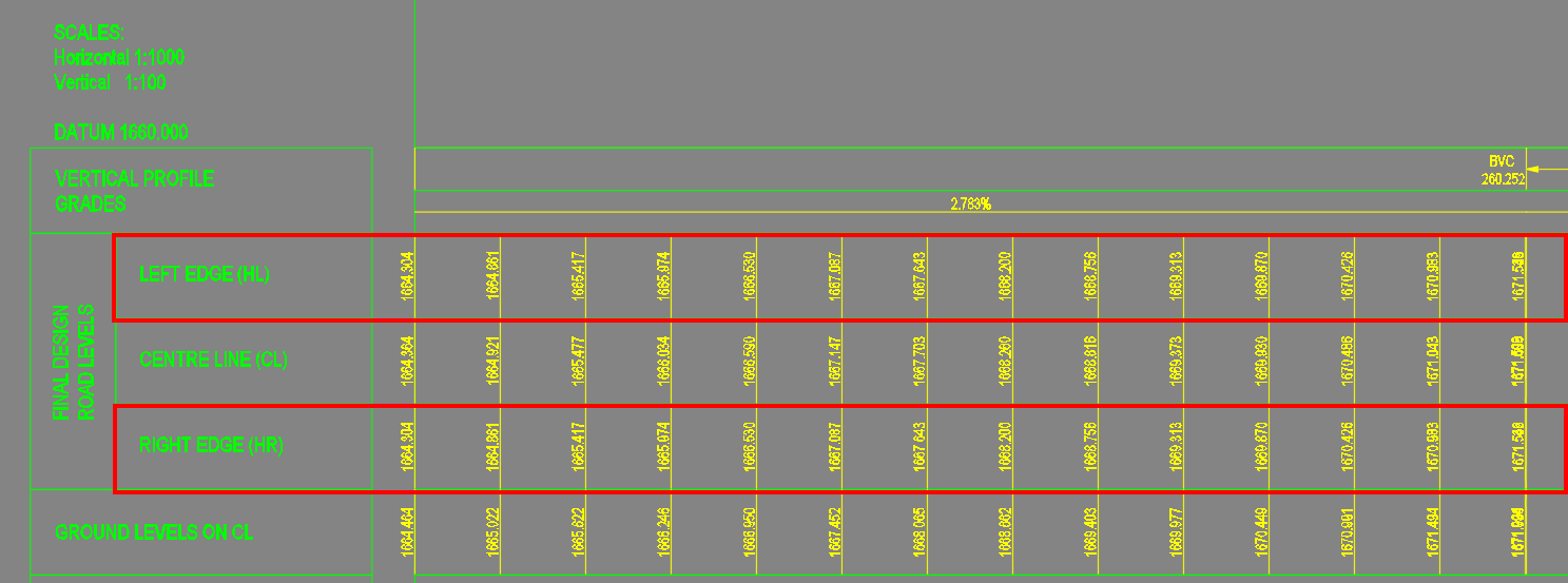
Road edge profiles - in many countries, the road edge elevations need to be displayed in profile views:
-
Drainage, guardrails and barrier line details displayed in the profile view – a user can create simplified profiles from corridor feature lines that can be used for profile views to display start and end chainage, length and description. The example below shows the concrete v-drain displayed in plan and in the profile view: **Plan:
**

**Profile view:
**

-
Corridor feature lines used as vertical targets for other corridors – a user can link corridor point codes to a profile that can be used as a target for another corridors. This option is preferred because it results in a smaller drawing size and the drawing management is easier (the user does not need to create feature lines from a corridor).
Location on Compact Ribbon:
Location on Extended Ribbon:
Link a Point Code to a Profile:
-
Click on the command in the ribbon.
-
In the command line choose the Code option:
-
The command line will prompt you to select a corridor. Select a corridor in the drawinf:
-
In the dialog you can link the point codes from the corridor to the existing profiles, or you can create new profiles. You can link each point code to two different profiles for the left and right side. The first profile (the Profile column in the image below) will update a profile based on the feature lines defined by the point code and will use all the elevations from the feature line. The second profile (the Simplified Profile column in the image below) will update a profile using just the start and end elevation of the feature lines.
The Simplified Profiles are useful for displaying information in the data bands of a profile view that need to show the start and end chainage, for instance showing where barrier kerbs would be constructed, or guardrails' location etc.
-
To check which profiles are linked to the corridor codes, open the Profiles from Codes window again (repeat steps 1-3 mentioned above).
Profiles linked to the corridor codes are dynamic but they only update when the Rebuild Corridors Command.
Or when the Rebuild Feature Profiles Command is used. This command updates all the corridors profiles at once.
Link a Feature Line to a Profile:
-
To create dynamic feature lines from a corridor, use the Civil 3D Corridors – Utilities – Create Grading Feature Line from Corridor command:
-
Tick Create dynamic link to the corridor:
-
Click on this command in the ribbon.
-
Select the feature line in the drawing. The command gives the option to select either an alignment or a profile. If an alignment is used a new profile is created, if a profile is used the profile elevations are linked to the feature line elevations (this is applicable for existing profiles). The image below shows the available settings for a new profile.
The created profile can be used for the profile view bands.
Troubleshooting Problems with Profile Feature Line Command
The Profile Feature Line command will not link a profile to a corridor feature line if the feature line has Connect check box unchecked in the Corridor Properties window: