EPANET CommandDifficultyintermediateAdded2027.0StatusdraftImport EPANET INP Command
Description:
Imports a water network from a EPANET INP file (.inp). This command Imports all the geometry and analysis properties supported by iDAS (it does not import quality properties as iDAS does not support water quality analysis).
Location on Compact Ribbon:
Location on Extended Ribbon:
Instructions:
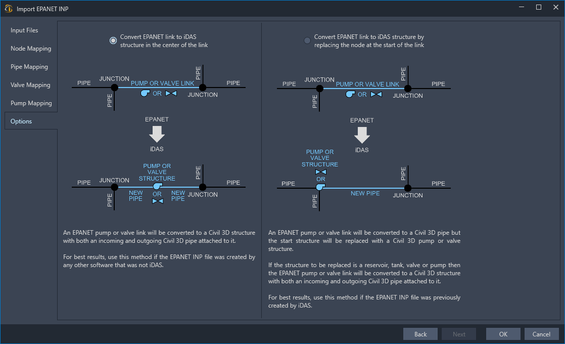
EPANET models pumps and valves as links whereas iDAS models them as structures (nodes). This means that a conversion has to take place while importing the EPANET model. This also means that an additional pipe needs to be created for each valve and pump imported.
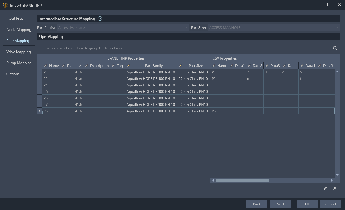
EPANET is also limited in the data that can be stored in the INP file. Therefore, this command allows the mapping of a CSV file that can contain pipe, pump and valve (links) names with associated data for each link. If the CSV is mapped then the properties from the CSV will appear in the mapping grids next to the links. This is particularly useful if the INP was exported from software that contains additional information about the links and allows the network to also be exported to a CSV (e.g. shapefiles).
-
Run the command.
-
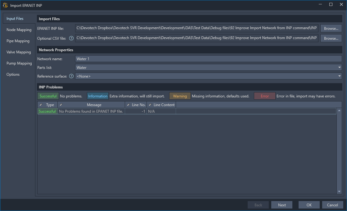
On the Input Files page select the files to import and setup the network properties. A list of possible issues with the INP file will be listed in the INP Problems section.
-
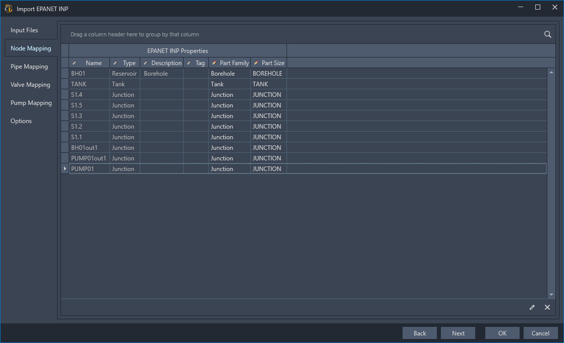
On the Node Mapping page select nodes and then right-click to choose part sizes from the parts list to apply to the nodes. Ensure that all nodes are mapped and that there are no <None> part sizes. You can click on the column headers to sort and filter the grid.
-
On the Pipe Mapping page select pipes and then right-click to choose part sizes from the parts list to apply to the pipes. You can click on the column headers to sort and filter the grid. If the pipes in the INP file contain intermediate vertices then the Intermediate Structure Mapping section will become enabled and allow you to specify the structures to use for the vertices. Ensure that all links are mapped and that there are no <None> part sizes.
-
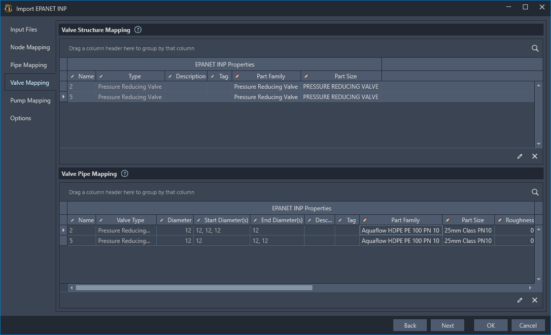
On the Valve Mapping page select valves and then right-click to choose part sizes from the parts list to apply to the valves. This must be done for structures and pipes as the INP link has to be converted to a Civil 3D structure and pipe. A roughness coefficient must also be specified for the pipes that will be created from the valves as this information is not available in the INP. Ensure that all nodes and links are mapped and that there are no <None> part sizes.
-
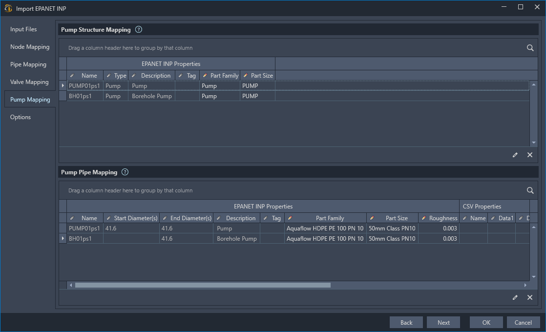
On the Pump Mapping page select pumps and then right-click to choose part sizes from the parts list to apply to the valves. This must be done for structures and pipes as the INP link has to be converted to a Civil 3D structure and pipe. A roughness coefficient must also be specified for the pipes that will be created from the pumps as this information is not available in the INP. Ensure that all nodes and links are mapped and that there are no <None> part sizes.
-
On the Options page choose the method to be used when converting the INP file to Civil 3D/iDAS network.
-
Click the OK button and the import will begin.
-
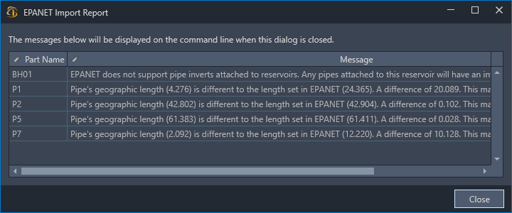
Once the import it completed a dialog will be displayed with a summary of errors, fixes or warnings that were encountered during the import process. Review the results and decide if you wish to use the created network, otherwise go to the source program that created the INP, fix any issues then reimport the INP into Civil 3D.