Network
Find Part Command
Description:
Zooms to where a specific pipe or structure is in the plan or any profile view. The pipe or structure can be specified by using its name or by selecting it a plan or profile view.
Location on Compact Ribbon:
Location on Extended Ribbon:
Instructions:
-
-
-
- Run the command.
-
-
- Select the pipe or structure in plan or profile view or type a Pipe or Structure Name and select it from the list, Civil 3D will then zoom to its location.
Structure in plan:
The same structure in the profile view:
Create Parts along Route Command
Description:
Allows users to create pipes and structures between two stations along an alignment. The pipes' and structure' elevations are determined from a profile that belongs to the selected alignment. Structures are inserted at alignment PI points and, optionally, at profile PVI points.
Location on Compact Ribbon:
Location on Extended Ribbon:
Instructions:
-
Run the command.
-
Specify the parts to create, the start and end stations, and the elevation options:
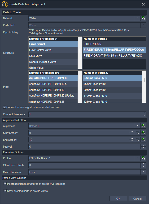
Note: when specifying the start and end stations you can optionally pick structures instead of stations. The station of the structure will then be calculated from the specified alignment.
Delete Parts along Route Command
Description:
Allows users to delete all pipes and structures between two structures. The pipes and structures along the shortest connected route between the two selected structures are deleted.
Location on Compact Ribbon:
Location on Extended Ribbon:
Instructions:
-
Run the command.
-
Select the start structure in plan or in a profile view:

-
Select the end structure in plan or in a profile view:

-
Choose the desired option:

Match Parts to Profile Command
Description:
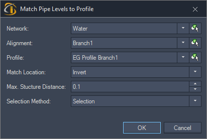
Allows users to update pipes' and structures' elevations from a profile between two structures. This allows parts to follow a design profile. No additional pipes or structures are created.
Location on Compact Ribbon:
Location on Extended Ribbon:
Instructions:
-
Run the command.
-
Specify the match profile properties:
-
Depending on the Selection Method chosen you will be presented with different selection prompts:


Create Vacuum Lift Command
Description:
Creates a saw-tooth vacuum lift between two structures. Various options can be set for calculating the vacuum lift geometry.
Location on Compact Ribbon:
Location on Extended Ribbon:
Instructions:
-
Run the command.
-
Click on the selection button, then select a start and end structure either from plan or profile view.

-
Select the part sizes to use for the structures and pipes that will be created as the vacuum lift.

-
Choose how the lift must be created.
- Start with lift will start the lift with an upslope (otherwise start with downslope)
- End with lift will end the lift with an upslope (otherwise end with downslope)
- Erase parts along route deletes existing parts connected between the start and end structures. Useful for replacing existing parts.
-
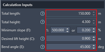
Specify the slopes, height and bend angle to use for the lift.
-
The calculated results will display the lengths and count of the parts that will be created.

-
You can also specify the surface, min. cover and max. cover to display in the preview graph.
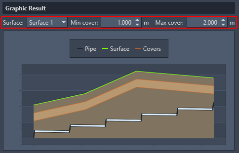
Below is the entire dialog with all values displayed.
Resulting geometry:
Swap Parts Command
Description:
Swaps multiple pipes and structures at the same time. The default Autodesk Civil 3D command only swaps one structure or pipe at a time. Pipes and structures can be selected either in the plan or profile view.
Location on Compact Ribbon:
Location on Extended Ribbon:
Instructions:
-
Run the command.
-
Click the selection button and select pipes and/or structures from model space. Pipes and structures can be selected from plan and/or profile views:

-
If the parts need to be filtered to specific networks then select/deselect the networks from the drop-down. The parts list will change depending on the network selection and can be changed as needed:

-
If structures need to be swapped then ensure that the Swap Structures checkbox is checked and choose a structure family and part size from the lists that the structures must be swapped to. The select button at the top right can be used to select a structure family and part size from an existing structure.

-
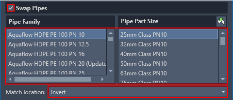
If pipes need to be swapped then ensure that the Swap Pipes checkbox is checked and choose a pipe family and part size from the lists that the pipes must be swapped to. The pipe Match location must also be specified and will determine the elevation on the pipe that will be held if the internal diameter of the new pipe part size is different from the selected pipe. The select button at the top right can be used to select a pipe family and part size from an existing pipe.
-
When a part is swapped the description is overridden to match the part size name as per the parts list. If the description must be retained the option to keep the description can be checked. When a part is swapped the part data is reset to the default data in the parts list. If the part data must be retained the option to keep part data can be checked. This option will attempt to keep as much part data as possible, but is the new part does not contain a part property then that part data cannot be kept.

-
Click the OK button to perform the swap.
Below is the complete dialog with all options selected:
Ref Alignment Command
Description:
Automatically sets the reference alignment for pipes and structures that are along an alignment. Pipe network stations are driven by a reference alignment which must be assigned to pipes and structures. Setting up the reference alignments for networks with multiple branches is a very time-consuming task especially for larger networks. This command automates the process of assigning reference alignments.
Location on Compact Ribbon:
Location on Extended Ribbon:
Instructions:
If no alignment exists or if the alignment is not properly aligned, no alignment is assigned to the pipes and structures. The image below displays an alignment which is not properly aligned with the pipes and structures (the alignment does not match with the pipe centerline):
-
To assign the reference alignments to pipes and structures run the command.
-
If you want to check which pipes or structures don't have a reference alignment assigned, select the pipe or structure in plan view, right-click and use the Edit Network command from the menu:
-
Click on the Pipe Network Vista command:
-
Select the Pipes or Structures and sort the objects by the Reference Alignment:
-
If you see question marks for the Distance in the profile view bands**,** it means that a reference alignment was not assigned to these pipes (the Distance band displays the pipe chainage, not the structure chainage since multiple alignments from different branches can go through a structure but only one alignment can go through a pipe, a pipe can belong only to one branch). Once you click on the Automap command, the alignment which goes through the pipes and structures will be assigned as a reference alignment and the chainage values will appear in the bands.
Before:
After:
Ref Surface Command
Description:
Sets a reference surface for all pipes and structures of a selected network.
Location on Compact Ribbon:
Location on Extended Ribbon:
Instructions:
-
Run the command.
-
Specify the Network Name and Reference Surface:

Update Network from Source Command
Description:
Compares the pipes of two networks and changes the pipe style based on the verification parameters. This is useful for comparing a surveyed network to a GIS network.
Location on Compact Ribbon:
Location on Extended Ribbon:
Instructions:
-
Run the command.
-
Select the source and destination networks. The destination network is the network that the styles will get applied to.

-
Select the styles to be applied to the pipes. The Verified style is used for pipes that are considered the same based on elevation and maximum distance apart. The Updated pipe style will be applied to pipes that are updated to match the source network. The Invalid style will be applied to the pipes that are not equal to the source.

-
Specify the parameters that are used to determine equality.

-
Click OK and the verification will begin and the styles applied.
Below is the entire dialog with all values displayed.
Remove Duplicates Command
Description:
Deletes duplicated objects (pipes and structures). Duplicated objects (objects on top of each other) might cause several issues with analysis, alignments etc.
Location on Compact Ribbon:
Location on Extended Ribbon:
Instructions:
-
Run the command.
-
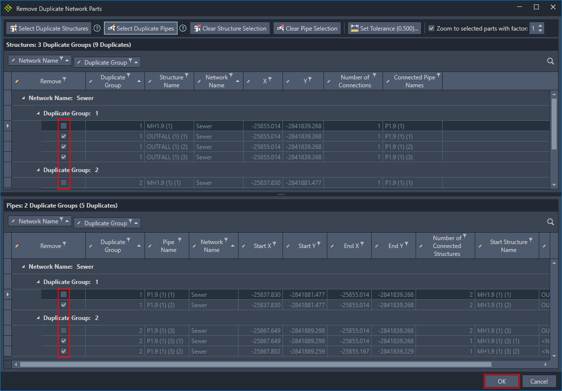
Select the structure or pipe you want to remove by clicking on the checkboxes and then click Ok to close the dialog and delete the parts:
-
Pipes and structures can be automatically selected for removal by clicking the Select Duplicate Structures and Select Duplicate Pipes buttons

-
The current selection can be cleared by clicking the Clear Structure Selection and Clear Pipe Selection buttons:

-
A tolerance can be set, which is the maximum distance 2 pipes or structures must be apart for them to be considered duplicates. If the tolerance is changed the duplicate pipe and structure tables will be cleared and repopulated with duplicates that fall within the new tolerance. The Set Tolerance button shows the current tolerance distance in use:

-
If the Zoom to selected parts with factor checkbox is checked, then when clicking on pipes or structures in the tables, model space will zoom to the current selection. The distance the camera is zoomed in by can be controlled by the factor amount. The higher the factor the further out the camera is zoomed:

Note that the tables can have their data and columns filtered or grouped in order to more easily determine which duplicates to be removed. For example, the duplicated structures can be grouped by network, thus allowing just duplicates from one network to be selected.
Remove Parts Outside Command
Description:
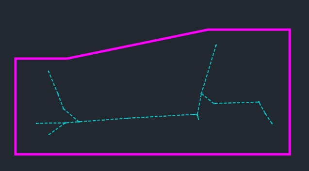
Deletes all parts in a single network that fall outside the extents of a selected polyline.
Location on Compact Ribbon:
Location on Extended Ribbon:
Instructions:
-
Run the command.
-
Select a polyline from model space:

-
Select a part from a network in model space:


 Before After
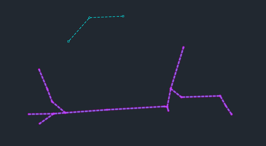
Display Connected Parts Command
Description:
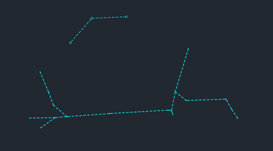
Highlights or selects all parts in a network that are connected to a single structure. This is used to interrogate a network to discover if any parts are disconnected or connected incorrectly.
Location on Compact Ribbon:
Location on Extended Ribbon:
Instructions:
-
Run the command.
-
Choose to either highlight or select the parts. If you choose to highlight parts you will need to REGEN the drawing to clear all highlights.

-
Select a structure in model space from the plan area.

 Before After
Find & Replace Descriptions
Description:
Finds and replaces text in a pipe or structure description.
Location on Compact Ribbon:
Location on Extended Ribbon:
Instructions:
-
Run the command.
-
Choose the type of network part to select:

-
Select the parts:

-
Provide the text to replace:

-
Provide the new text to replace the old text with:

-
The modifications will be displayed on the command line:

Edit User Fields Command
Description:
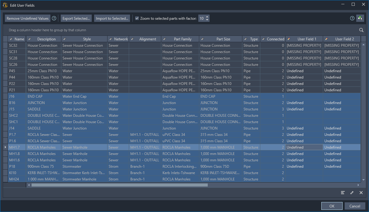
Batch edits User Defined Fields for multiple pipes and structures. The User Defined Fields can also be exported and imported.
Location on Compact Ribbon:
Location on Extended Ribbon:
Instructions:
-
Run the command.
-
Select the pipes and structures whose User Defined Fields are to be updated.
-
In the grid select the pipes or structures to edit, then right click in the cell of the column (field) that is to be edited. Next, start typing, hit enter, and all the selected rows will be updated.
-
Use the Remove Undefined Values button to replace any User Defined Fields that contain the value Undefined with blank text.
-
Use the export and import buttons to save and load the User Defined Fields to and from a CSV file. This is useful if parts are going to be swapped. Swapped parts lose their User Defined Fields, so the fields can first be exported to a CSV file, then the parts swapped, and then the fields reimported from the CSV file.
-
When selecting parts in the grid, modelspace will be zoomed to the selected parts if the Zoom to selected parts with factor checkbox is checked. The zoom factor can be changed, the larger the number the further out it will be zoomed.
-
Use the selection button to select a pipe or structure from the modelspace. If the pipe or structure is already in the grid it will be selected. Note that the selection button will not add additional parts to the grid.
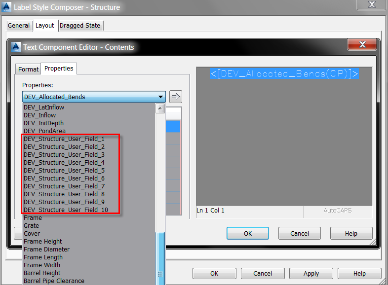
A User Defined Field can be used for labels, profile view bands and tables:
Result:

Apply Property Set Command
Description:
Applies existing property set data to various pipe and structure properties. This is useful if property set data was imported with the import shapefile command and the properties need to be applied to a network later.
Location on Compact Ribbon:
Location on Extended Ribbon:
Instructions:
The pipe and structure properties that can have property set data is limited and the property set data has to be compatible with the part property (e.g. a property set data value cannot contain alphabetic characters if being used for a pipe invert elevation).
-
Run the command.
-
Select pipes and/or structures to apply property set data to:

-
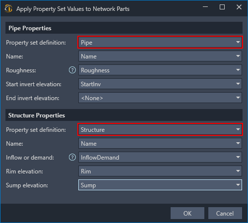
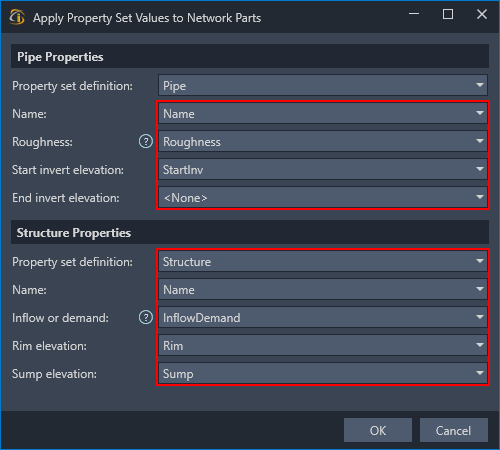
In the dialog that is displayed choose the property set definitions to use for the pipe and structure properties:
-
Next map the property set data to the structure and pipe properties.
-
Click OK to start updating the pipe and structure properties with the property set data.
Create or Update Expressions
Description:
The expressions for pipe network plan and profile labels get sometimes corrupted when drawing is opened in the different Civil 3D versions. This command creates or updates these expressions.
Location on Compact Ribbon:
Location on Extended Ribbon:
Instructions:
-
Run the command.
-
At the command line the number of expressions that were updated/created are displayed:

-
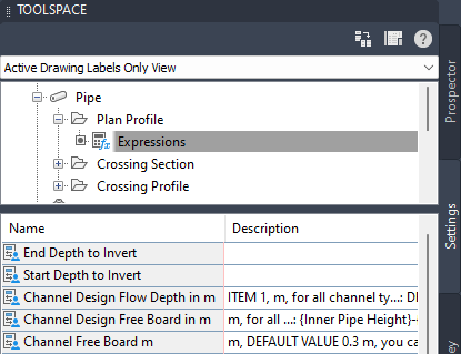
In the Settings tab in the Toolspace palette the expressions are available:
Network Legend Command
Description:
Creates a pipe network legend from all the structures available in a specific network. The created table is an AutoCAD table and is not dynamic.
Location on Compact Ribbon:
Location on Extended Ribbon:
Instructions:
- To create a legend table, run the command.
- Specify the table properties:
Created table:
Some blocks might be too big or too small (it is on our wish list to fix it automatically), double-click on the block and adjust the scale:
Result:
Manage Part Property Sets Command
Description:
Links property set fields to network part and analytical data.
Location on Compact Ribbon:
Location on Extended Ribbon:
Instructions:
For more details see the video on our Training Videos web site, channel Pipe Networks (General): https://www.devotechgroup.com/pipe-networks-training
Run the command. This is the command window that is displayed:
Export to GIS Command
Description:
Exports a network to GIS including property set data.
Location on Compact Ribbon:
Location on Extended Ribbon:
Instructions:
-
Click the select button and then select the pipes and structures from model space that must be exported.

-
Select the property set definitions that must be exported for the structures and pipes. Multiple property set definitions per pipe or structure can be exported.

-
Specify a GIS file (shapefile or geopackage) to create for both structures and pipes. If either a structure or pipe output file is omitted, then a file will not be created for that part type. Note that it is recommended to use a geopackage rather than a shapefile, as shapefiles have a limit on the number of characters a field can have, so long property set field names will be truncated.

-
If a geopackage is to be created, then the property set definition's name can be added as a prefix to the geopackage field names. This is useful if multiple property set definitions are exported that contain the same field names.

Below is the entire dialog with all values displayed.
Pipe Catalog Settings Command
Description:
Displays the pipe catalog settings dialog, allowing the user to enable/disable the pipe catalog settings dialog at startup and to set the current Civil 3D pipe catalog to the catalog that was last used in the drawing, the iDAS default catalog, the default Autodesk US metric catalog or to browse for another catalog.
Location on Compact Ribbon:
Location on Extended Ribbon:
Instructions:
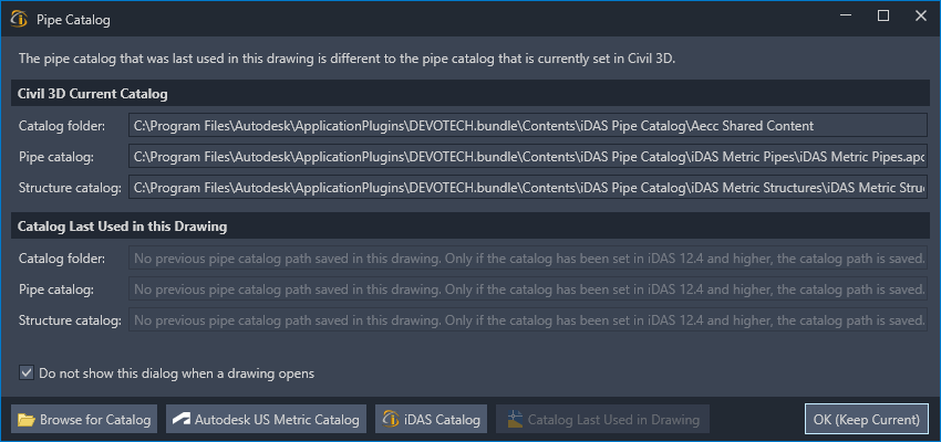
When a drawing is opened the Pipe Catalog dialog is displayed if the catalog that is set in Civil 3D is different from the catalog that was set when the drawing was last open. The dialog will also show if no catalog has ever been set for the drawing and the text "No previous pipe catalog path saved in this drawing.
The dialog displays the current catalog set in Civil 3D and the catalog saved in the drawing. The following options are available:
- Catalog Last Used in Drawing Set the Civil 3D catalog to the catalog that was last saved in the drawing.
- OK (Keep Current) Keep the current catalog set in Civil 3D
- Use iDAS Pipe Catalog Set the Civil 3D catalog to the default iDAS catalog
- Browse for Catalog Browse for another catalog not listed.
- Autodesk US Metric Catalog Use the United States metric catalog (C:\ProgramData\Autodesk\C3D 2024\enu\Pipes Catalog)
- **Do not show this dialog when a drawing opens **If checked this dialog will not be displayed when a drawing is open and there is a catalog conflict.
If the user needs to access the dialog while a drawing is open then
-
Run the command.
-
Choose an option:
Note: if the Civil 3D catalog or the catalog saved in the drawing is missing, the text "**MISSING PATH**" will be displayed before the path text.