Pipes
Swap Conduits Command
Description:
Swaps multiple pipes at the same time. The default Autodesk Civil 3D command only swaps one pipe at a time. Pipes can be selected either in the plan or profile view.
Location on Compact Ribbon:
Location on Extended Ribbon:
Instructions:
This command is the same as the Swap Parts Command except the dialog layout is configured for swapping pipes instead of swapping pipes and structures.
Grade Pipes Command
Description:
Calculates the slope between two selected pipes and assigns the slope to all the pipes between the selected pipes. Pipes can be graded in the chainage direction or against the chainage direction.
Location on Compact Ribbon:
Location on Extended Ribbon:
Instructions:
-
Run the command.
-
Select the first and last pipe between which you want a constant slope (select in the profile view):
-
Choose whether or not a drop must be applied to the first structure that was selected:

-
Select the part of the pipe that must be matched when grading:

-
Specify the drop amount that must be applied at each structure:

-
Choose how to provide the slope amount. If the Pipe option is chosen then an existing pipe will need to be selected whose slope will be used for the grading. If Value is chosen then the slope will need to be provided:

-
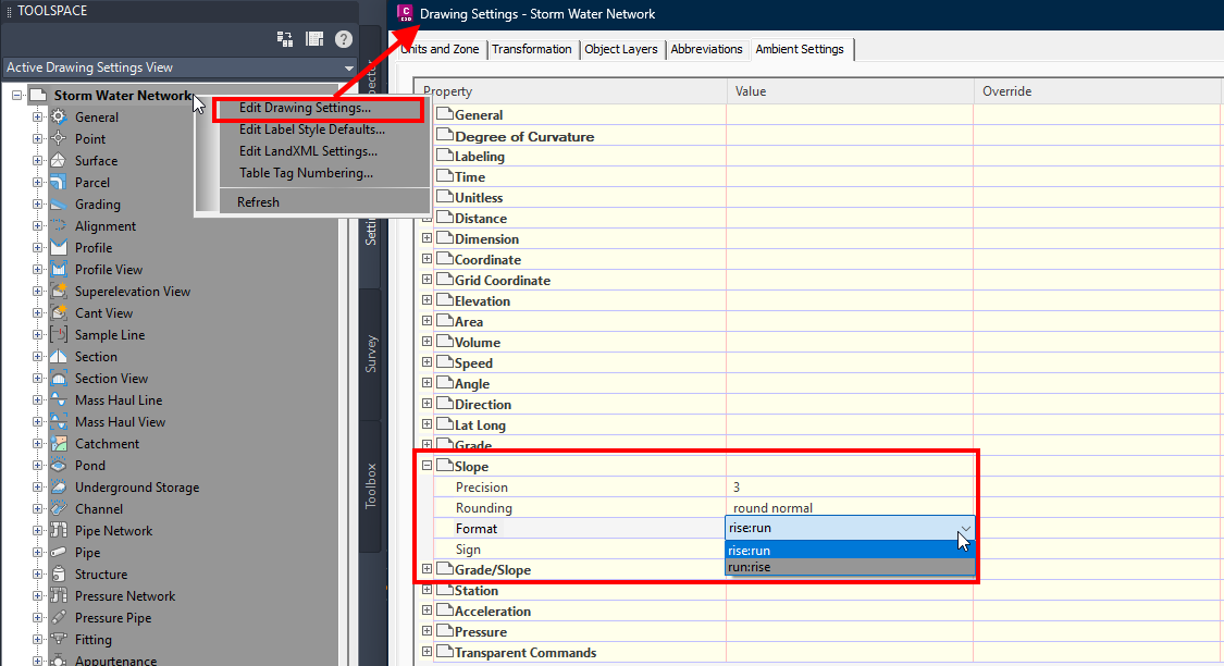
If Value was chosen in the previous step, then the slope can now be provided in either a percentage or in ratio formats. The ratio format is taken from the Edit Drawing Settings – Ambient Settings – Slope. It can be set to either rise:run or run:rise:
The calculated slope between the two chosen structures will be displayed in the command line and be set as the default slope option:

Before:

After:

Adjust Inverts Command
Description:
Sets the pipe invert levels, structure invert levels and sump depth for the entire pipe network or just for a specific branch. This is useful for water pipe networks where it is often required that pipes follow the ground levels at a specific depth
Location on Compact Ribbon:
Location on Extended Ribbon:
Instructions:
-
-
-
- Run the command.
- Specify the Invert Level, Reference Surface and the objects you want to apply the function to:
-
-
Before:
After:
This command can also be used for sump depth adjustment for stormwater and sewer networks:
Before:
After:
Match Pipe Inverts Command
Description:
Updates a single pipe's levels based on adjacent pipes' level. This allows for easy matching of levels to other pipes or creating drops relative to adjacent pipes.
Location on Compact Ribbon:
Location on Extended Ribbon:
Instructions:
-
Run the command.
-
Choose if both sides of the pipe (Both) must be updated or only one side (Single)

Both:
-
Select a pipe from plan or profile view that will be updated.

-
Select the first pipe to get levels from. If a drop is specified (in a future prompt) then the drop height will be subtracted from this pipe's level and applied to the pipe that is to be updated on the side that it is connected to through a structure.

-
Select the next pipe to get levels from. If a drop is specified (in a future prompt) then the drop height will be added to this pipe's level and applied to the pipe that is to be updated on the side that it is connected to through a structure.

-
Specify which pipe level location must be used to match levels to.

-
Provide a drop that will be added/subtracted from connected pipes' levels and will be applied to the pipe that is to be updated. If a zero drop is provided then the pipes' levels will match.

-
The command will continue in a loop to allow another pipe to be updated.
Before After
Single:
-
Select a pipe from plan or profile view that will be updated.
-
Select the a pipe to get levels from. If a drop is specified (in a future prompt) then the drop height will be subtracted from this pipe's level and applied to the pipe that is to be updated on the side that it is connected to through a structure.

-
Specify if the pipe's level must be updated with a drop or if a drop and slope should be applied.

-
Specify which pipe level location must be used to match levels to.
-
Provide a drop that will be added/subtracted from connected pipes' levels and will be applied to the pipe that is to be updated. If a zero drop is provided then the pipes' levels will match.
-
If dropSlope was chosen then you will be prompted for a slope. The slope will be applied away from the structure that connects both pipes and a negative value will apply the slope on a downhill away from the structure.

-
The command will continue in a loop to allow another pipe to be updated.
Before: Drop After: Drop
Before: Drop and Slope After: Drop and Slope
Connect Pipes Command
Description:
Connects disconnected pipes to structures. If pipes are not connected various commands will not work properly, e.g. the Manage and Analyze / Pipe Manager analysis will not run, the Civil 3D renaming command will not work, the alignment from pipe network command will not work etc.
Location on Compact Ribbon:
Location on Extended Ribbon:
Instructions:
- To connect pipes to structures, run the command.
- Click on Connect All:
Result:
Before (masking is switched on): After
Break Pipe Command
Description:
Breaks a pipe into two pipes at an indicated point or at a structure location. If the pipe is broken at a structure location the two pipes are then connected to the structure. This is useful for joining an existing structure to an existing pipe.
Location on Compact Ribbon:
Location on Extended Ribbon:
Instructions:
-
Run the command.
-
Select a pipe to break from model space:

-
Select how the pipe is to be broken, either at a Structure or at a Position:

-
If Structure is chosen then select a structure in model space that is close to the pipe.

-
If Position is chosen click on a position that is close to the pipe. The pipe will be broken at a location perpendicular to the pipe passing through the indicated position.

-
Divide Pipe Command
Description:
Divides a pipe exceeding a specified maximum length. It is useful for any pipe network where a maximum distance between structures/manholes needs to be defined.
Location on Compact Ribbon:
Location on Extended Ribbon:
Instructions:
-
Run the command.
-
Define the properties:
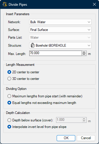
Max. Length – any pipe that is longer than specified Max. Length will be divided. 2D center to center - the pipe length is measured in 2D plan projection.
3D center to center – the pipe length is measured along the pipe in 3D space.
Maximum lengths from pipe start (with remainder) - the pipe is divided at fixed intervals equal to the Max. Length value, with a remainder that is shorter than Max. Length value. This method is commonly used for bulk pipelines.
Equal length not exceeding maximum length – the pipe is divided into equal segments that do not exceed the Max. Length value. This approach is typically used for stormwater and sewer networks.
Depth below surface (cover) – the specified depth is applied to both, the start and end of the pipe.
Interpolate invert level from pipe slope – the pipe depth is calculated from the divided.
IMPORTANT If the Length Measurement is set to 3D center to center, Dividing Option is set to Maximum lengths from pipe start (with remainder), and the Depth Calculation is set to Depth below surface (cover) then the final 3D length may not exactly match the Max. Length. This is because variations in pipe slope can affect the actual 3D length.
-
Select the pipes to divide.
Before:
After dividing the pipe:
Convert Straight to Curved Pipe Command
Description:
Converts straight pipes to curved pipes along an alignment. If pipes are offset from the alignment there is an option to move the pipes and connected structures onto the alignment while curving them.
Location on Compact Ribbon:
Location on Extended Ribbon:
Instructions:
-
Run the command.
-
At the command line choose the method of selecting pipes and then select them:

-
Choose the method of selecting an alignment. Either choose to use a reference alignment associated with the pipes or choose to select an alignment from model space:

-
Choose whether or not to move the pipes that are offset from the alignment onto the alignment (see images below for results):

Pipes and alignment before the command is run:
Pipes after the command is run with the option not to move the pipes onto the alignment:
Pipes after the command is run with the option to move the pipes onto the alignment:
Pipe Crossing Station Command
Description:
Update pipes' and/or alignment's names or descriptions with the station of an alignment that crosses the pipe or alignment. This is useful for renaming culverts to the station of the corridor (alignment) that they cross.
Location on Compact Ribbon:
Location on Extended Ribbon:
Instructions:
-
Run the command.
-
Select the type of entity to change the name or description of:

-
Select pipes and/or alignments to change the name or description of:

-
Select an alignment that crosses the selected pipes and/or alignments:

-
If a pipe is to be renamed you will be presented with the option of setting the reference alignment of the pipe to the alignment that crosses it.

-
Choose the desired property to update:

-
Type in text that will be used as a prefix to the station value:

-
Type in text that will be used as a suffix to the station value:

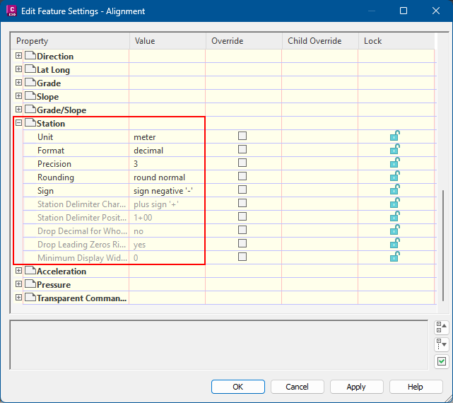
Note that the station value and format will match the Civil 3D alignment station settings under Toolspace - Settings - Alignments - Edit Feature Settings - Station. Make sure to change these setting prior to running the command: