Survey Grid Command
Description:
Creates a survey grid within a polyline's extents. The grid is drawn with the COGO points.
Location on Compact Ribbon:
Location on Extended Ribbon:
Instructions:
Survey Grids are often necessary for civil engineering projects. To create grids, first draw a closed polyline to specify the area in which you want to create the survey grid.
-
Click on the command in the ribbon.
-
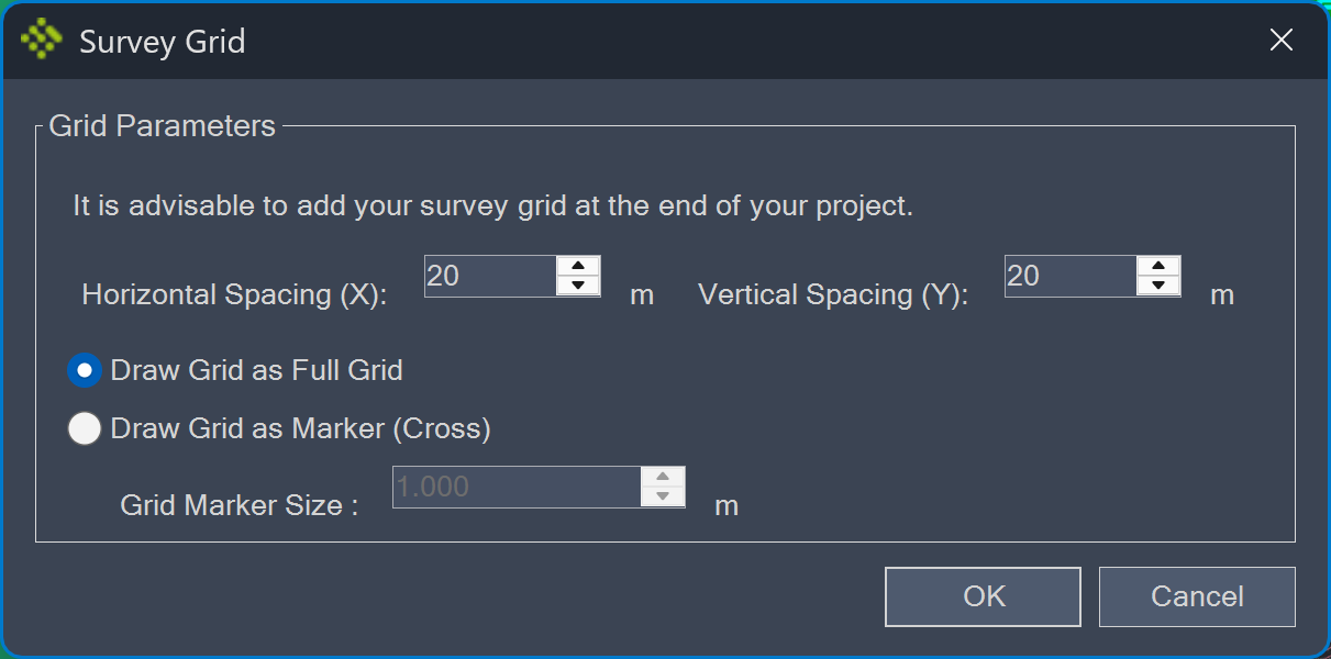
Specify the grid spacing. If you select Draw Grid as Marker (Cross), the Grid Size option becomes available. Otherwise, the grid lines will be created as continuous lines (full grid):
-
Select OK and select the polyline that indicates the border of the survey grid.
The survey grid point style and label style are not driven by the point group. There are two options to change the point style or style (e.g. X and Y values should not be swapped and multiplied by -1):
Option 1:
-
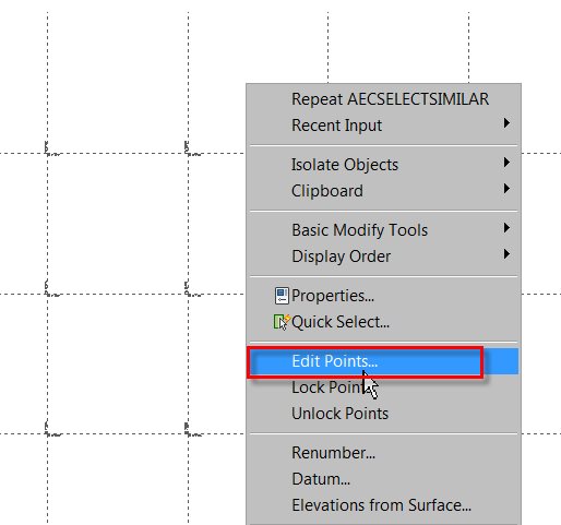
Select points, right-click and use the Edit Points command from the menu:
-
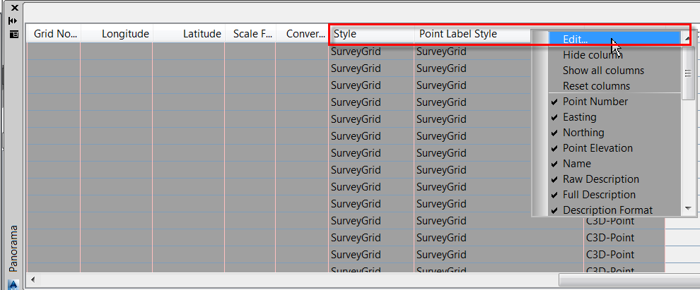
Right-click on the Style or Point Label Style heading and use the Edit command:
-
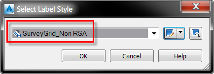
Specify the style to be used (the image below shows the label style which does not swap X and Y coordinates and the values are not multiplied by -1, the coordinates displays the Civil 3D model space coordinates):
-
If the label style is set to <None> the points will display a label which is set in the SurveyGrid point group's Properties. In the Prospector go to the SurveyGrid point group, right-click and select Properties:
-
Set the point label style to <None>:
Option 2:
-
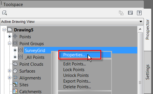
In the Prospector, go to the SurveyGrid point group, right-click and select the Properties command:
-
Go to the Overrides tab and override the point Style and Point Label Style:
-
If you only need to move the X or Y coordinate, select the label, hover the mouse over the rectangular grip point and select the Toggle sub item grips command:
-
It gives two other grip points, one for the X coordinate and one for the Y coordinate:
-
The labels can be moved independently:
TIP: Create a survey grid in a new empty drawing and XRef it into your plan production drawings to keep your design drawing as small as possible.