Assemblies Folder (support files)
This folder contains the Devotech Civil 3D Assemblies.dwg drawing which provides typical assemblies and subassemblies. This drawing also includes South African kerb subassemblies. The drawing can be opened directly from the following path:
C:\Program Files\Autodesk\ApplicationPlugins\DEVOTECH.Bundle\Contents\Support\
Assemblies
Or it can be opened with the command DTECH_ASSEMBLIESFILE.
South African kerb subassemblies:
The folder also contains subassemblies in a .pkt format (see the How to Import Subassemblies from PKT File chapter for details on how to use .pkt files):
Devotech_Conditional_Road_Edge_Beam_or_Channel_Ver_01.pkt
Devotech_Channel_on_Low_Side_Ver_01
Devotech_Lane_Ver_02.pkt
Devotech_SANRAL_Cut_Fill_Ver_01.pkt
Devotech_SANRAL_Cut_Fill_Ver_02.pkt
Devotech_SANRAL_Cut_Fill_Ver_03.pkt
Devotech_SANRAL_Cut_Fill_Ver_04.pkt
Devotech_SANRAL_Cut_Fill_Ver_05.pkt
Devotech_SANRAL_Cut_Fill_Ver_06.pkt
Devotech_SANRAL_Cut_Fill_Ver_07.pkt
Devotech_SANRAL_Cut_Fill_Ver_08.pkt
Devotech_SANRAL_Cut_Fill_Ver_09.pkt
Devotech_SANRAL_Median_Barrier_1-4m_with_Retaining_Wall_Ver_02.pkt
Devotech_SANRAL_Median_Barrier_1-4m_with_Retaining_Wall_Ver_03.pkt
Each subassembly contains the version in its name. Devotech provides all the released versions to ensure that users can work on the older projects without any issues.
iDAS Conditional Curb Subassembly
This subassembly allows users to specify different curb types for high and low road edge sides. For example, on the high side, a semi-mountable curb can be used, on the low side, a non-mountable curb with a channel can be used:
It can also be used to add a channel on the low side in the cut condition (it can be used together with the conditional cut fill subassembly):
To watch the video on how to use this subassembly, use the link below, otherwise follow the steps further down:
Attach this subassembly to the road edge, the image below shows four iDAS Conditional Curb subassemblies:
The following parameters can be set:
Layout Width
Specifies the subassembly width in the layout mode:
Layout Grade
Specifies the subassembly slope in the layout mode (positive up, negative down):
Default Cross Slope
This parameter is used to get the cross slope value from the lane. You can use any default value because it should always be referenced to the lane slope if superelevation is not used. Referencing the lane slope is the prefered option instead of the superelevation because the calculated superelevation cross slope can be overriden by profile targets.
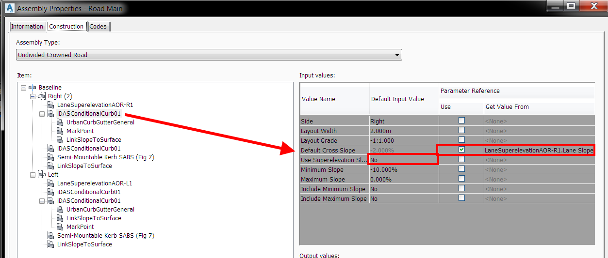
To reference a subassembly to the lane slope, go to the Assembly Properties window, tab Construction, select iDAS Conditional Curb subassembly, tick Use Reference Parameter and select Lane Slope (cross slope):
Note: The Use Superelevation must be set to No, otherwise superelevation will be used.
Use Superelevation Slope
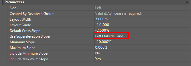
If you do not want to reference a subassembly to the lane slope or if you know that no profile targets are used for lanes, you can use superelevation.
Minimum Slope
Specify the minimum cross slope value for the required condition. For the high side, the value is mostly set to 0%, for the low side, this value is set to a minimum value, e.g. -10%:
Maximum Slope
Specify the maximum cross slope value for the required condition. For the low side, this value is mostly set to 0%, for the high side, this value is set to a maximum value, e.g. 10%:
Include Minimum Slope
You must specify which condition must be applied at the 0% cross slope or at the cross slope where two conditions are overlapping. If you set the Include Minimum Slope to Yes for the high side condition, it will apply this condition to the 0% cross slope:
In this case, Include Maximum Slope (see further) should be set to No for the low side condition:
Include Maximum Slope
You must specify which condition must be applied at the 0% cross slope or at the cross slope where two conditions are overlapping. If you set Include Minimum Slope to Yes for the high side condition, you should set the Include Maximum Slope to No for the low side condition to ensure that Civil 3D will not apply both conditions at the 0% cross slope.
Link code in the layout mode:
The link code in the layout mode automatically displays the conditions applied:
If you want to make the text bigger, you must change the link code text height for the <default> codes:
Result:
It will change the text size for all the <default> codes so it might cause some subassemblies to have codes on top of each other, see the guardrail below:
The other option is to import link codes into Assembly code set style and set the Label Style. The link code is the same as specified condition (if you change the condition, you must import new code into the Assembly code set style):
Troubleshooting
If subassembly creates both conditions, then there might be one of the following problems:
-
Subassembly is not referenced to the lane cross slope:
-
Subassembly is not set to use a superelevation:
-
Alignment superelevation is not defined.
Versions and fixes:
iDAS-Conditional Curb-2016-1.0 (19.11.2019)
iDAS-Conditional Curb-2016-1.1 (28.02.2020)
iDAS-Conditional Curb-2016-1.2 (29.02.2020)
iDAS-Conditional Curb-2016-1.3 (14.11.2020
iDAS-Conditional Curb-2016-1.4 (23.11.2020)
iDAS-Conditional Curb-2018-1.5 (23.5.2022)
iDAS-Conditional Curb-2016-1.1
Fixed error FailedConversion from string "" to type 'Date' which appeared on some of the computers in the Event Viewer. This error caused the subassembly to fail and all the conditions were always created:
iDAS-Conditional Curb-2016-1.2
Fixed error: Failed Conversion from string to DateTime...
iDAS-Conditional Curb-2016-1.3
Fixed error: Failed Conversion from string to DateTime...
iDAS-Conditional Curb-2016-1.4
Fixed error: Failed Conversion from string to DateTime...
iDAS-Conditional Curb-2016-1.5
Fixed error Your iDAS license is not valid which. was provided even if iDAS license was valid.
Devotech Channel on Low Side
This subassembly creates a channel on the low side of the road:
Attach this subassembly to both sides of the road and connect other subassemblies to them. If the condition is not fulfilled, then this subassembly is not created and only the following subassemblies are created. Assembly example is shown below:
The following paramters can be set:
Devotech Lane Subassembly
Application and major benefits
This subassembly is suitable for dual carriageway design and there are five major advantages which the standard Civil 3D lane subassembly does not support:
-
It has inside and outside widths
-
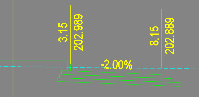
It has inside and outside shift widths (practical if the lanes have a stepped offset on the inside and outside):
-
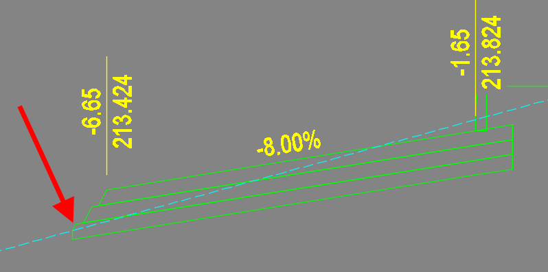
It supports box cut:
-
Most of the codes can be set by the user.
-
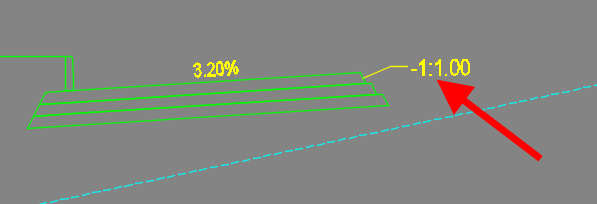
An outer sloped edge does not superelevate with the lane, but it keeps the defined slope:
Usage guidelines
-
Multiple subassemblies can be linked together to ensure the designer won't be limited by a maximum number of lanes:
-
If you link slope to another subassembly, then the Use Superelevation parameter must be set to None:
-
To use a box cut you must define a target surface for the subassembly in the corridor properties:
Parameters
The following parameters can be set for Devotech Lane Subassembly:
Improvements
Version 03 improvements
Update date: 2025-10-16
New icon and updated name in Tool Palettes
The icon was added to subassembly, and the Tool Palettes description now uses spaces instead of underscores to improve readability.
Copyright and usage restriction
The Copyright and Usage Restrictions were added to subassembly:
Parameter headers
The parameter headers were added to the Properties window for easier navigation:
Use Box Cut parameter bug fix
Fixed a bug that applied box cut condition as soon as the target surface was set regardless of Use Box Cut parameter being set to No.
Subassembly displays in skew cross sections
Civil 3D has a bug that if a subassembly contains zero-length link, then the subassembly is not displayed in skew cross sections. The Devotech Lane Subassembly was updated to not to contain any zero-length links even if some width parameters are set to "0", e.g.: Inside Shift Width.
Devotech SANRAL Cut Fill Subassembly
Specification and usage guidelines
This subassembly creates cut/fill as per SANRAL's specification for rural roads:
It supports the following four conditions:
Low fill:
High fill:
Type A concrete side drain:
Shallow and deep cut:
The SANRAL's specification does not specify if a berm should always be created or only under specific conditions, thus you can specify under which circumstances the berm should be created when in cut:
- Always
- Only When Surface Cross Slope is Towards Road
- Never
This setting is available in the Properties window:
Example of the berm created in the cut condition only when surface cross slope is towards the road:
If you use the option to create a berm Only When Surface Cross Slope is Towards Road, then this condition can change every few meters and it might create a lot of very short berms. To solve this issue, you can define a horizontal target (polyline, feature line, alignment or survey figure) and if this target exists then the berm will always be created in the cut condition. This target must be set in the Corridor Properties window under Set All Targets:
Below is an example of a short berm which was connected with another berm by using a horizontal target:
Before: After:
Berm in 3D view:
A similar problem can occur if the condition for deep cut or high fill, changes every few meters. You can define a horizontal target (polyline, feature line, alignment or survey figure) and if this target exists, then deep cut or high fill will always be created. This target must be set in the Corridor Properties window under Set All Targets:
SANRAL's specification does not specify if a high fill drain should always be created or only if the road cross slope is towards the road edge. This subassembly has an option to create a high fill drain under the following conditions:
- Always
- Only When Cross Slope is Towards Road Edge
- Never
This setting is available in the Properties window:
The image below shows a high fill drain only on the low side of the road:
The SANRAL Cut Fill Subassembly contains a point code Slope_Pattern which can be used to create a corridor slope pattern for cut and fill. For the second feature line (Feature Line 2) use the Daylight code:
It also creates a pattern at the transitions between cut and fill:
If Attach Berm to Drain Outside Point in Shallow Cut is set to Yes, the subassembly:
- Always creates a berm in shallow cut
- Does not create cut/fill or shallow cut bench
- Adds the point code Shallow Cut Deep Cut Daylight Point Code to the drain outside point.
This parameter was designed mainly to be used for overrides in the Corridor section editor, therefore, its default value is set to No:
The image below shows the cross-section when the parameter was set to No in the corridor section editor (note the short daylight link):
After this parameter was set to Yes:
Settings in the Corridor section editor:
The Shallow Cut Bench Width parameter is mostly used for transitions between shallow cut and deep cut (its default value is set to 0):
If this parameter is set to 0, the subassembly does not create a zero length or a bench link at all to avoid issues with the cross-sections not being parallel to the corridor baseline (Civil 3D bug).
Shallow cut bench transition:
SANRAL's cut/fill specification does not cater for all possible scenarios which can occur on a real project. If the surface is very steep and berms are desired, the subassembly won't give an acceptable solution although it is correct as per SANRAL's specification, see the image below with cut on the left-hand side and the created berm and rounding:
To fix this, create an assembly and apply it to the corridor region along the chainage where the problem occurs.
Parameters
The following parameters can be set for the Devotech SANRAL Cut Fill Subassembly:
Notes:
Level Drain Bottom Width is driven by the Shallow Cut Drain Backslope Width.
If you want to override the Low Fill Slope, set the same values for the Min and Max slopes.
Shallow Cut Bench is used as a transition between Shallow Cut and Deep Cut. It is not defined in the SANRAL specification.
Override Condition to parameter overrides any condition to the specified condition. It can be used in situations where only once specific condition must be used. If various condition should be applied then rather override condition with targets.
Improvements
Version 16 improvements
The following parameters were added:
- Unsurfaced Shoulder Width in High Fill
- High Fill Shoulder Rounding (Yes/No)
- Guardrail Distance from Road Edge
The subassembly displays an icon in the Tool Palettes:
Version 17 improvements
The level drain backslope slope is now driven by Shallow Cut Drain Backslope Slope and not by Cut Slope. This change will provide more flexibility to the designers in solving the problems as shown in the image below:
The Shallow Cut Drain Backslope Slope parameter displayed in the properties window:
Version 18 improvements
The following six parameters were added to the subassembly:
Deep Cut Range1 Max Depth
Deep Cut Range2 Max Depth
Deep Cut Range3 Max Depth
Deep Cut Range1 Slope
Deep Cut Range2 Slope
Deep Cut Range3 Slope
The parameters displayed in the Properties Window:
These parameters allow changing the deep cut slope based on the deep cut depth. There are three ranges available. If the depth falls into the specific range, then the slope is applied for the entire deep cut:
Example of the range 0-2 m:
Example of the range 2-5 m:
If the Shallow Cut Max Depth is set to 1.5 m and the Deep Cut Range1 Max Depth is set to 2 m, then the Deep Cut Range1 Slope is only used for the depth 1.5-2 m.
Version 19 improvements
The following parameter was added into the subassembly:
Shallow and Deep Cut Depth Measurement Offset (0=Shoulder Break Point)
User can define where the point for cut depth calculation is positioned. The previous subassembly versions calculated the cut depth at the Shoulder Break Point, see the blue arrow in the image below. The red arrow shows the offset and depth measurement if the value bigger than 0 is used:
Version 20 improvements
Fixed a bug where using target for fill trimming on the left-hand side provided an incorrect result:
Version 21 improvements
Fixed a bug where fill slope never used a positive value if the Create High Fill Drain parameter was set to Never:
In the example below, the deep cut condition was overridden to high fill with the slope value being positive (going up). The daylight link (gray line) was not created:
The following image shows the result when updated subassembly was used:
Version 22 improvements
-
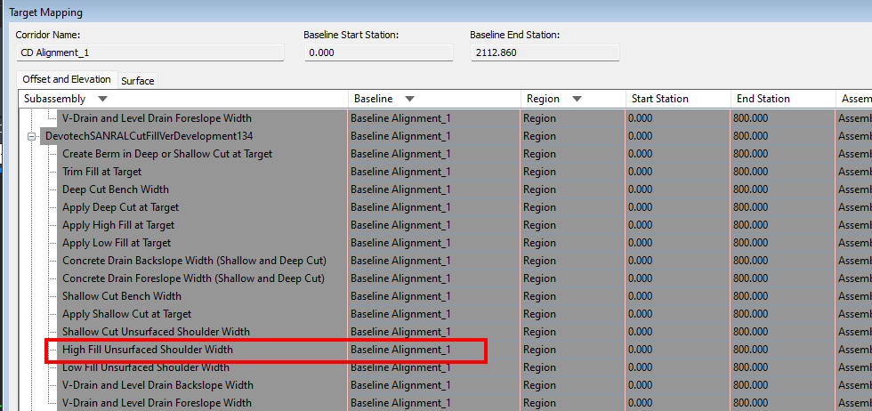
A new target parameter High Fill Unsurfaced Shoulder Width was added to override the width of unsurfaced shoulder in the high fill condition:
-
Fixed a bug that caused the unsurfaced shoulder in high fill condition to not to change the shoulder width if the high fill drain was not used.
Version 23 improvements
Update date: 2025-10-04
Cut range depth measurement offset bug
Fixed a bug where deep cut range depth was not measured at the depth measurement offset but at the shoulder break point:
Copyright and usage restrictions
The Copyright and Usage Restrictions were added to subassembly:
Parameter headers
The parameter headers were added to the Properties window for easier navigation:
Known issues
The parameters and headers appear in the wrong order in the Subassembly Properties window:
The same issue appears in the Properties window if the Apply Tool Properties to Subassembly command from Tool Palettes is used:
The headers are then displayed at the bottom of the Properties window and the parameters are sorted alphabetically:
Parameters renaming
Some parameters were renamed to improve the navigation in the Properties window.
Old name New name
Create Bern in Shallow Cut X Berm in Shallow Cut
Create Berm in Deep Cut X Berm in Deep Cut
Guardrail Point Code X High Fill Guardrail Point Code
Guardrail Offset from Road Edge X High Fill Guardrail Offset from Road Edge
Version 24 improvements
Update date: 2025-10-08
Fixed a bug that caused the parameters and headers to appear in the wrong order in the Subassembly Properties window.
Before:
After:
Version 25 improvements
Update date: 2025-10-16
The icon was updated to match the color scheme, and the Tool Palettes description now uses spaces instead of PascalCase to improve readability.
Devotech SANRAL Median Barrier with Retaining Wall Subassembly
Specification and usage guidelines
This subassembly creates a median with multiple conditions as per SANRAL's specification. It can be applied from the start to the end of the road without specifying separate regions with different assemblies, it designs the complete road through all the different conditions. It can be inserted at the median or it can be inserted between the two adjacent roads, e.g. between a dual carriageway and a collector road. User can also specify, whether the drains should be added or not. The examples below show a few conditions at the median and between two roads:
Note: The dual road and the collector road in the images below were modelled as two separate independent corridors. They were linked together by using horizontal and vertical targets.
An example with drains:
Example without drains:
The left and right inside road edges can be targeted to the alignments and profiles:
If you want to use this subassembly between two adjacent roads, attach it to an auxiliary LinkWidthAndSlope subassembly:
The LinkWidthAndSlope subassembly can be found in the Tool palettes, Generic tab:
The width of the LinkWidthAndSlope should be equal to the distance from the road edge to the centre of the median barrier subassembly. This distance can be overridden by horizontal targets. The other settings should match the image below:
Parameters
The following parameters can be set for Devotech SANRAL Median Barrier with Retaining Wall Subassembly:
Improvements
Version 02 improvements
Bug fixes and enhancements.
Version 03 improvements
Bug fixes and enhancements.
Version 04 improvements
Bug fixes and enhancements.
Version 05 improvements
Bug fixes and enhancements.
Version 06 improvements
Bug fixes and enhancements.
Version 07 improvements
The new parameters were added:
- Create Drain on Left
- Create Drain on Right
Version 08 improvements
Update date: 2025-10-16
Copyright and usage restriction
The Copyright and Usage Restrictions were added to subassembly:
Parameter headers
The parameter headers were added to the Properties window for easier navigation:
New icon and updated name in Tool Palettes
The icon was added to subassembly, and the Tool Palettes description now uses spaces instead of underscores to improve readability.
Devotech SANRAL Median Barrier with Wall and U Channel Subassembly
This subassembly applies different types of barriers or retaining walls to the corridor, depending on the difference in elevation between the left inside lane and right inside lane profiles. These profiles can either be designed for each side of the road or they can be created from a corridor (Devotech iDAS tools can be used to link these profiles dynamically to the corridor). The following barrier types are used in the subassembly:
Median Barrier Type: MB (Max 125mm Level Difference):
Detailed specification:
Median Barrier Type: MC (Max 500mm Level Difference):
Detailed specification:
Median Barrier Type: MD (Max 650mm Level Difference):
Detailed specification:
Median Barrier Type: ME (Max 950mm Level Difference):
Detailed specification:
Median Barrier Type: MF (Max 1.380mm Level Difference):
Detailed specification:
The following parameters can be set:
The user has the following display options for the channel (Show Drainage Channel):
- When the lane slope towards the barrier
- Always show channel regardless of the lane slope
- Never
The following corridor Slope and Elevation Targets need to be set to determine the elevation difference between the left inside lane and right inside lane:
The following suggested point codes could be added to the top layer of the corridor for the left inside and right inside lanes. It is important to change the point code label style from Section | Offset | Elevation to Section | Offset | Elevation | Extension Left and Section | Offset | Elevation | Extension Right respectively, to display the correct label style in the cross-sections.
-
The point label style can be changed in the Corridor code set style. Go to Toolspace – Settings – General – Multipurpose Styles – Code Set Styles and double click on the Corridor code set style:
-
Go to the Codes tab:
-
Change the label styles for ETWIL and ETWIR:
Result:
Devotech Conditional Road Edge Beam or Channel Subassembly
This subassembly applies different conditions for low and high road edges. It uses an edge beam on the high side and a concrete channel on the low side:
The following parameters can be set:
If you need a transition line between the edge beam and channel then use the Transition code for the Edge Beam Outside Top Point Code and Channel Outside Top Point Code, see the image on the previous page:
If the transition is close to the corridor frequency point, then the transition will be very short:
There is no quick solution to create proper a transition between two different objects.
Devotech Conditional Road Edge Barrier Kerb and Channel Subassembly
This subassembly applies different conditions for low and high road edges. It uses a barrier kerb on the high side and a concrete channel with a barrier kerb on the low side:
The following parameters can be set:
Devotech Conditional Road Edge CK5 Kerb or MK10 Kerb Subassembly
This subassembly is based on the City of Cape Town standard details. It applies a CK5 kerb on the low side of the road and a MK10 kerb on the high side of the road. The subassembly includes the option to use a sidewalk and the minimum width of the sidewalk can be specified. The width of the CK5 and MK10 kerb differs, therefore the subassembly automatically widens the sidewalk to make up for the difference in kerb widths. The distance from the edge of travel way to the outside edge of the sidewalk is the same on the high and low side of the road. This subassembly also has a dedicated parameter to define the shift width of the layer underneath the kerb. The user must assign the lane superelevation to the subassembly to calculate the slope of the lane and determine whether the kerb is situated on the low or high side of the lane. This subassembly can also be used where elevation targets are applied to the corridor.
CK5 (Low Side)
MK10 (High Side)
The following parameters can be set:
The user needs to select each subassembly and assign the lane superelevation parameter. This will determine whether the correct kerb configuration is on the high or low side of the road. Elevation targets overwrite superelevation in Civil 3D, therefore the following changes need to be made to the assembly:
-
Select the assembly centerline, right-click and select Assembly Properties from the menu:
-
Go to the Construction tab, select the Devotech Conditional Road Edge subassembly on the Right Baseline:
-
Set the Lane Slope Parameter Reference to Right Lane Layer 1.CrossSlope and the Superelevation to None:
-
Select the second layer called Right Lane Layer 2 on the Right Baseline:
-
Set the Width Parameter Reference to Right Lane Layer 1.BottomWidth, Shift Width Parameter Reference to Right Devotech Conditional Road Edge subassembly Curb Layer Shift Width and Default Cross Slope Parameter Reference to Right Lane Layer 1.Cross Slope:
-
Select the Devotech Conditional Road Edge subassembly on the Left Baseline:
-
Set Lane Slope Parameter Reference to Left Lane Layer 1.CrossSlope and Superelevation to None:
-
Select the second layer called Left Lane Layer 2 on the Left Baseline:
-
Set the Width Parameter Reference to Left Lane Layer 1.BottomWidth, Shift Width Parameter Reference to Left Devotech Conditional Road Edge subassembly Curb Layer Shift Width and Default Cross Slope Parameter Reference to Left Lane Layer 1.Cross Slope:
How to Import Subassemblies from PKT Files
Subassemblies in a .pkt format can be imported directly into Civil 3D's Tool Palettes. It is good practice to import subassemblies into a custom tab in the Tool Palettes, the workflow below shows how to create a new tab.
-
Open the Tool Palettes, right-click on any tab and select New Palette from the menu**:**
-
Specify the name (any name can be used):
-
Right-click on the tab and select the Import Subassemblies command from the menu:
-
Browse to the provided .pkt file and click OK:
The imported subassembly:
Note: If you open a drawing containing a subassembly that was not imported into your Civil 3D yet, import the subassembly into the Tool Palettes and restart Civil 3D. If you do not restart Civil 3D, you may not be able to modify subassembly parameters or rebuild corridors, and Civil 3D may give you an error.