Horizontal Alignments (HA)
An alignment is typically used for features such as road centrelines, pavement edges and drainage centrelines. Alignments can represent existing features or proposed features.
Alignments are the first of the three primary design features to be laid out by the designer. Profiles and cross-sections provide the other two design features necessary for a full three-dimensional description and modelling of the proposed linear structure such as roadways, channels, etc.
Alignment Creation Tools (create alignment by layout)
-
Go to Home in the ribbon and click on the Alignment – Alignment Creation Tools command:
-
Specify the Name, Alignment Style and Alignment Label Set (chainage labels):
-
Click on the first icon from the left-hand side in the Alignment Layout Tools toolbar and select the Curve and Spiral Settings command to set up the default values for curves and spirals. This step is not necessary if the default values are suitable for the design:
-
Specify the default values:
-
Click on the first icon from the left-hand side in the Alignment Layout Tools toolbar and select the Tangent-Tangent (With Curves) command to draw the alignment tangent polyline.
The horizontal alignment with chainage labels:
The Alignment Layout Tools toolbar has various tools to adjust an alignment. Below are the tools which are used regularly.
Insert point of intersection (PI):
Delete PI:
Add a curve to a PI. This command needs to be used if the new PI is inserted into an alignment. New PIs do not contain curves:
If a curve must be deleted (sometimes curves prevent major changes to the horizontal alignment because the software cannot find a solution to fit in the curve with specific parameters), use the Delete Sub-entity command.
If the radii must be set to a specific value, the grid view is the right place to do so:
Note 1: Autodesk's suggestion is to use the Undo and Redo commands from the Alignment Layout Tools toolbar when adjusting alignments:
Note 2: If you need to reopen the Alignment Layout Tools toolbar, select an alignment in plan, right-click and use the Edit Alignment Geometry command from the menu:
Create an Alignment from Objects
Civil 3D can create alignments from the following objects: lines, arcs and polylines. These objects can either be part of the current drawing or they can be XRefed.
Draw a polyline with the standard AutoCAD command. Polylines can be drawn with or without curves, but it is much easier to use a polyline without curves. It is difficult to manipulate polylines with curves as there might be a problem with tangency. Civil 3D can automatically add curves to tangent polylines during the conversion to an alignment.
-
Go to the Home tab in the ribbon and click on the Alignment – Create Alignment from Objects command and select the polyline:
-
Specify the alignment direction:
-
Specify the Name, Alignment Style, Alignment Label Set (chainage labels) and Default Radius:
The created alignment:
Alignment Properties
You can use the Alignment Properties dialog box to assign a unique name and style to the alignment, establish station equations and assign design speeds (these are used for superelevation calculation). The Alignment Properties dialog box contains tabs for Masking, Point of Intersection definition and Constraint Editing.
To open the Alignment Properties window, select an alignment in plan, right-click and select the Alignment Properties command from the menu:
Alignment Chainage Labels
-
Select an alignment, right-click and select the Edit Alignment Labels command from the menu:
-
Click on the Import label set button and select a suitable set.
Result:
Alignment Labels
Various alignment labels can be applied to an alignment. Some labels will be used in the Setting Out Data Tables chapter.
-
To add labels, go to Annotate in the ribbon and use the Add Labels – Alignment – Add Alignment Labels command:
-
Specify the Label type, Station offset label style, Marker style, click Add and follow the command line:
Result:
Setting Out Data Tables
Alignment with Horizontal Curves
Before a setting out data table can be created, the labels must be added to the horizontal alignment.
- Use the label settings shown in the image below and select the first tangent:
Label START will be added to the tangent:
- Change settings according to the image below, select each curve individually and the last tangent:
Labels add a PI description with a number to each curve as well as END to the last tangent. Once all the required segments have labels, the table can be created.
-
Go to Annotate in the ribbon and use the Add Tables – Alignment – Add Segment command:
-
Specify the Table Style and Alignment. There is an option to Select by label or style which allows the selection of labels from the drawing:
Styles with RSA in front of YX swap the X and Y coordinates and multiply them by "-1". If you work in South Africa or the drawing is in the third or fourth quadrant of the coordinate system, then styles with RSA YX should be used. Text (For BCC | PI | ECC Label) means that it can be used when BCC | PI | ECC curve labels are used, see image below:
Setting out data table:
Straight Alignment
Before a setting out data table can be created, labels should be added to the horizontal alignment.
-
Use the label settings as shown in the picture below and select straight alignment:
-
Go to Annotate in the ribbon and use the Add Tables – Alignment – Add Segment command:
-
Specify the Table Style (use only styles which contains For Straight Alignment in the description) and Alignment. There is also an option to Select by label or style which allows the selection of labels from the drawing:
Styles with RSA in front of YX swap the X and Y coordinates and multiply them by "-1. If you work in South Africa or the drawing is in the third or fourth quadrant of the coordinate system, then styles with RSA YX should be used.
Setting out data table for straight alignment:
Note: To switch off alignment labels, used for the table creation, freeze the C3D−No Plot Object layer:
Superelevation
Superelevation Basics
Undivided roads
-
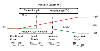
The following illustration shows an undivided road as a corridor type and a crowned cross-section shape. During superelevation, the simple crowned roadway undergoes adverse crown removal. In this illustration, the adverse crown removal is the distance from End Normal Crown to Reverse Crown:
-
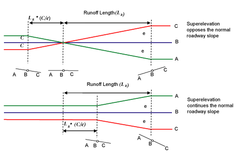
The following illustration shows an undivided road as the corridor type and the cross-section shape is planar. There is no crown, therefore no removal of adverse crown is necessary. This type of roadway typically has a downward slope in one direction on the unsuperelevated sections. Because of this, the distance required to achieve full superelevation varies depending on whether the superelevation continues in the direction of the downward slope or superelevates in the direction opposite to the normal downward slope. This example is typical for off-ramps, one-way traffic roads, and some service roads.
Divided roads:
-
The following illustration shows a divided road as the corridor type and the cross-section shape is planar. The roadway undergoes adverse crown removal during superelevation:

-
The following illustration shows a divided road as the corridor type and a crowned cross section shape on each side. The roadway undergoes adverse crown removal during superelevation. This option is barely used in South Africa:

Calculate Superelevation
-
Go to the Alignment Properties (select alignment, right-click and choose the command Alignment Properties from the menu), then go to the Design Criteria tab to specify the design speed, which must be used for superelevation calculation:
-
Select the alignment in the plan view and click on the Superelevation – Calculate/Edit Superelevation command from the contextual ribbon (green ribbon):
-
Select the Calculate Superelevation Now option, which opens the superelevation calculation wizard:
-
Specify the roadway type and Pivot Method. The Pivot Method is basically the superelevation rotation point.
-
Specify the Normal Lane Width, which will be used for the superelevation runoff length calculation:
-
If the shoulder needs to have a different superelevation, then it can be specified under Shoulder Control. Most of the time the South African roads have the same shoulder superelevation as the road lanes, so the shoulder does not need to be calculated:
-
Specify the Infrastructure Design Automation Suite (iDAS) design criteria file, various files will be available as shown in the picture below. Otherwise use the AASHTO file, which is very similar to the South African standards:
Design criteria files:
- It is also practical to tick Automatically Resolve Overlaps. Once you click Finish, the superelevation is calculated and the superelevation manager opens. The calculated values can be overwritten manually if needed.
Note 1: Once the superelevation is calculated, it will override the default slopes of the assembly, see the Corridors chapter.
Note 2: The subassembly should be set to use the superelevation values, see the Corridors chapter.
Define Superelevation Manually (suitable for township roads)
The superelevation of township roads are often driven by the stormwater management and not by the centrifugal forces. Therefore, it is more suitable to define the superelevation manually instead of an automatic calculation which adds superelevation to each horizontal curve.
-
Select an alignment in the plan view and click on the Superelevation – View Tabular Editor command from the contextual ribbon (green ribbon):
-
The superelevation can be added to any curve or to all of them. In the example below, all the superelevation critical values are added to the first curve. Select Curve.1 and click on the plus sign:
-
The superelevation should be defined for the entire alignment, start with a chainage of 0 (you can either snap to the beginning of the alignment or you can type 0 in the command line):
-
Right-click on the text Manual station, select the Assign Critical Station command and choose the correct critical point. The Devotech Civil 3D template displays the values Begin Normal Crown, End Normal Crown, Begin Full Super and for End Full Super in the profile view superelevation band, any of these critical points can be used. Even if you use Begin Normal Crown for all manual stations, it will not cause any issues. It is purely used for labelling the profile view superelevation band. If you do not assign critical points, the superelevation will work, the values will just not be displayed in the profile view superelevation band.
-
Specify superelevation for the Left Outside Lane and Right Outside Lane. Civil 3D has inside and outside lanes, most of the time the outside lanes are used for single carriageways:
Tip: If you see too many columns in the Tabular Editor, right-click on the column heading you do not want to see and use the Hide column command to only display the required columns:
- Follow the steps above for the other superelevation critical points. Do not forget to specify the superelevation End Station. The image below shows an example of the superelevation definition for an entire alignment:
Superelevation displayed in the profile view band without superelevation critical points assigned:
Superelevation displayed in the profile view band with superelevation critical points assigned (values and chainages are shown):
Note 1: Once the superelevation is defined, it will override the default slopes of the assembly, see the Corridors chapter.
Note 2: The subassembly must be set to use the superelevation values, see the Corridors chapter.
Define Superelevation for Straight Alignment Manually
Straight alignments are often superelevated for stormwater management. If you use the method described in the previous chapter, you will get the following message: "The selected alignment does not contain any curves":
-
To specify the superelevation for a straight alignment, select the alignment in the plan view and click on the Superelevation – Calculate/Edit Superelevation command from the contextual ribbon (green ribbon):
-
Select the Open superelevation curve manager option:
The superelevation curve manager can be used to:
- Navigate and view the superelevation calculation status and criteria for each curve
- Receive graphical feedback and navigate to locations in the drawing related to superelevation curves
- View information for transition in and out regions for each curve
- Access the Superelevation Tabular Editor
- Access the Superelevation Wizard
- View and edit the superelevation criteria used to generate superelevation data for curves that use calculated superelevation
- Create user-defined curves
-
Click on the Create user-defined curve button:
-
Select the straight alignment twice (the first entity is the same as the last entity) then press escape and click on the Tabular Editor button:
-
Select the User Defined curve and click on the Plus Sign to add a new chainage. Generally, the superelevation should be defined for the entire alignment, start with a chainage of 0 (you can either snap to the beginning of the alignment or you can type 0 into the command line).
-
Right-click on the text, Manual station, select the Assign Critical Station command and choose the correct critical point. The Devotech Civil 3D template displays the values Begin Normal Crown, End Normal Crown, Begin Full Super and for End Full Super, any of these can be used. If you skip this step, the superelevation will work, the values will just not be displayed in the profile view superelevation band.
-
Specify the superelevation for the Left Outside Lane and Right Outside Lane. Civil 3D has inside and outside lanes, in South Africa the outside lanes are mostly used for the design.
-
Follow the above steps for the other superelevation critical points. Do not forget to specify the superelevation End Station.
Defined superelevation on the straight alignment, transition at chainage 40-60m and 100-120m.
Note 1: Once the superelevation is defined, it will override the default slopes of the assembly, see the Corridors chapter.
Note 2: The subassembly must be set to use the superelevation values, see the Corridors chapter.
Superelevation View
-
Select an alignment in the plan view and click on the Superelevation – Create Superelevation View command in the contextual ribbon (green ribbon):
-
Specify the display options, most of the time the default settings can be used:
Created superelevation view:
Note: Superelevation can be modified with the grips in the superelevation view.