Vertical Alignments (VA) (Civil 3D essentials)
Profile View
A Profile View with the Profile View Bands represent a longsection. The profile view consists of grids and descriptions, while the profile view bands display information at the top or at the bottom of the longsection:
Before designing the road vertical alignment (road profile), the profile view must be created. Most of the time the design is related to the surface data, thus the standard workflow is to create the surface profile and then creating the profile view.
-
Go to Home in the ribbon and use the Profile – Create Surface Profile command:
-
Select an alignment and a surface, click Add and then click on Draw in profile view:
-
Specify the Profile View Style, it must correspond with the Profile View Band Set which will be used. The profile view style name contains the name of the band set it should be paired with e.g.: profile view Dual Road | Band Set 1 | Full Grid must be used with the band set Dual Road | Band Set 1 | km or Dual Road | Band Set 1 | m.
An example of profile view styles and bend sets that pertains to each other:
-
Specify the Station Range. Use the Automatic option if you want to create a profile view for the entire horizontal alignment. A profile view can only be created for a specific section if User specified range is selected:
-
Specify the Profile View Height. If the elevation range is unknown, it is better to use the Automatic option:
-
The Profile Display Options window shows the profiles that will be displayed in the profile view:
-
Specify the Data Bands. Band set names contain the purpose for which it should be used, the band set number and chainage units (km or m). Band set numbers are used because the template contains additional band sets for specific project types. For example, for a single road the template contains three band sets and every band set is available with the chainage in metres and kilometres:
Single Road | Band Set 1 | m
Single Road | Band Set 1 | km
Single Road | Band Set 2 | m
Single Road | Band Set 2 | km
Single Road | Band Set 3 | m
Single Road | Band Set 3 | km
- Civil 3D contains hatching for cut and fill areas in a profile view. Because the road's vertical alignment has not been created yet, do not add hatching and click on the Create Profile View button:
The created profile view with the surface profile:
Note: The bands are not displaying the correct data because the road's vertical alignment and left and right edges are not created yet.
Profile Creation Tools (create profile by layout)
Profile creation tools are used for the vertical alignment design.
-
In the Home tab of the ribbon click on the Profile – Profile Creation Tools command and select a profile view:
-
The Create Profile window allows users to specify the Name, Profile Style and Profile label set, the default values can be used. The name is automatically set to VA Alignment Name. VA stands for Vertical Alignment:
-
The Profile Layout Tools toolbar:
-
Before starting with the vertical alignment design, specify the default values for the vertical curves. Click on the black arrow next to the first icon from the left-hand side and select the Curve Settings command:
-
The default vertical curve parameters:
-
To design a vertical alignment as a tangent polyline, click on the black arrow next to the first icon from the left-hand side and use the Draw Tangents With Curves command:
A tangent polyline should start at the beginning of the profile view and end at the end of the profile view:
The Profile Layout Tools toolbar has various tools to adjust the profile. Below are the tools which are used most often:
Insert point of vertical intersection (PVI):
Delete PVI:
Add a curve to a PVI. This command needs to be used when a new PVI is inserted into a profile because it will not contain any curves. In road design, the parabola is used for vertical curves:
Raise / Lower PVIs command can raise or lower the entire profile or just a specific portion:
If a curve must be deleted (curves can prevent major changes being made to the profiles because the software cannot find a solution to fit the curve within the specific parameters), use the Delete Sub-entity command.
The Grid View should be used to set slope K values and when radii need to use specific values:
Note 1: Autodesk suggests that the Undo and Redo commands from the Profile Layout Tools toolbar, should be used when adjusting profiles:
Note 2: If you need to reopen the Profile Layout Tools toolbar select a profile in the profile view, right-click and select the Edit Profile Geometry command from the menu:
Modify Profile with Grip Points
When selecting the profile, grip points will display. These grip points can be used to modify the profile interactively:
Profile Properties
The Profile Properties can be reviewed in the Profile Properties window.
-
To open this window, select the profile in the profile view, right-click and select Profile Properties from the menu:
-
In the Information tab of the Profile Properties window, users can rename the profile and change the profile style:
Profile Labels
Multiple labels can be added to the profile.
-
Select the profile in the profile view, right-click and select the Edit Labels command from the menu:
-
Click on the Import Label Set button:
Select a label set. When designing a profile, the label set Grad | Radius | Length is suitable because it is "light" and it displays the necessary major information.
For final plotting the label set PVI Number can be used.
For stormwater drainage system designs, the label set High & Low Points | Chainage (m) | Elevation can be used.
Label sets which contain the word Band in the name are used for profile view bands. See the YouTube video on how to use these label sets https://www.youtube.com/watch?v=eiM7F-JNkW0.
The following profile label sets are available in the South African Civil 3D template:
Profile label set Grade | Radius | Length:
Profile View Properties and Band Set Settings
The profile view properties window allows users to change the profile view style, height, length, displayed profiles, band sets and hatching.
To open the profile view properties window, click on the profile view (select the profile view grid), right-click and select the Profile View Properties command:
The Information tab allows users to change the profile view style:
The Stations tab allows users to change the profile view length if the User Specified Range option is ticked:
The Elevations tab allows users to change the profile view height and to split the profile view (multiple datum levels can be used in one profile view; this is suitable for very steep surfaces). To change the profile view height the User Specified Height option must be ticked:
The Profiles tab allows users to switch the profile's display on and off in the profile view. Not all the profiles need to be displayed but their data can still be used in the profile view bands. Another way to switch off the profiles in the profile view is to change the style to _No Display, which can be done in the same tab:
The Bands tab allows users to change the band set and setting the correct profiles for the profile view bands. Click on the Import Band Set command to import bands:
Profile view bands need to read data from the profiles. For this purpose, Profile 1 and Profile 2 must be set. The band style name shows what should be set as Profile 1 and Profile 2. At this stage the profiles for the left and right edges are not available, they will only be created when the corridor is created, see the Corridors chapter for the details applicable to the road edges. NA means that the profiles are Not Applicable, it does not matter which profile is being used.
Profile 1 is used to define geometry points where the band details must be displayed (beginning of vertical curve, end of vertical curve, PVI, start, end, etc.). Profile 2 is used for the elevation values which are displayed in the band:
If you click OK, the profile view will display the correct information for all the bands, except for the left and right edges, see the Create Left and Right Road Edge Profiles for Profile View Bands chapter. Levels at the profile geometry points will also display (they are highlighted in the picture below):
The Hatch tab allows users to specify the hatching for profiles, e.g. cut and fill areas can be hatched accordingly:
Profile View Labels
-
Various labels can be added to the profile view. Go to the Annotate tab in the ribbon and select the Add Labels – Profile View – Add Profile View Labels command:
-
Specify the Label Type, Marker Style, click Add and follow the command line:
Notes for Working with Profiles and Profile Views
-
When moving a profile view select only the profile view grid or a profile view grip point and move the profile view. If you select the entire profile view using a selection window the labels might not move properly.
-
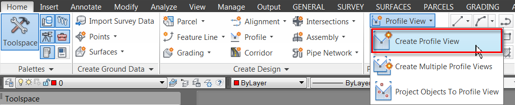
To create a new profile view, use the Profile View – Create Profile View command in the Home tab of the ribbon:
-
To delete a profile view, select only the profile view grid and use the delete command. If you select the entire profile view using a selection window, the profiles displayed in the profile view will be deleted as well.
-
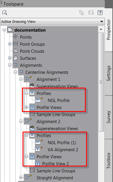
When a profile view and profiles are created, they automatically display in the Prospector. They can also be deleted from there (right-click on the object and click on the Delete command from the menu):