Create Profile View (longsection) for Pipe Network
Create Profile View Manually
Before you can create a profile view for a pipe network you have to create an alignment from a pipe network. In the ribbon go to Home – Alignment – Create Alignment from Network Parts, select the first structure of your pipe network (or branch) and then select the last structure of the network (or branch). When you press Enter, the Create Alignment window opens. Specify an alignment Site, Name, Type, style, and label set, you can also choose if you want to Create profile and profile view (Devotech suggests to always have this option ticked).
Note: For more details about alignment properties, label sets, adjustment etc. can be found in the CIVIL 3D ESSENTIALS − Horizontal Alignments (HA) chapter.
If the Create profile and profile view option is ticked, the profile view creation process will start automatically after the alignment creation.
In the Create Profile View window, General tab, specify the Profile view style in. The Profile view style name must correspond with the Profile view band set you intend to use.
Set profile view band set:
Create Profile View Automatically
Devotech iDAS has tools to create profile views and alignments automatically from a network. For sewer and stormwater networks use the Regrade Network. For bulk water pipelines use the Bulk Water Wizard.
Profile View Styles and Band Set Styles
Profile view styles and bands set styles must correspond. Meaning that if you use the profile view style Pipe | Storm | Levels at Structure then you must use the Pipe | Storm | Levels at Structure | m band set. The Devotech drawing template contains different styles and band sets for stormwater, sewer and water networks.
Profile view band sets:
Profile view styles:
There are two types of band sets in the Devotech template. The first type only displays information at the structures, it contains**...|Levels at Structure|...** in the description. The second type displays information at structures and at specific intervals (20m, 50m etc, it contains**...|Levels at Structure & Interval|...** in the description. The second type requires more attention from the user. Details are described in the following chapter.
Settings for Band Set Containing “Levels at Structure & Interval” in Description
The following band sets display values at structures and at specific intervals. They require additional input from the user.
-
Create profiles for the invert and trench by using the Profile Pipes command from the Profiles drop-down:
-
Select the network you want to create a profile for:
-
Tick Invert and Trench, click OK and select the profile view you want to create profiles for:
-
Go to the Profile View Properties, Bands tab and set the appropriate profiles for Profile 1 and Profile 2. This only needs to be done for the bands with the style name in CAPITAL LETTERS. The band name specifies which profiles must be used for the specific band.
-
If you don't want the profiles to be visible in the profile view, switch them off in the Profile View Properties, Profiles tab**.**
Profile View Band Labels Not in the Correct Position
If some labels are not positioned correctly, as shown in the picture below, go to the Profile View Properties and click OK. This will move the labels to the right position.
Profile View Labels Not Displayed
If you do not see labels in profile view bands you should check if the Data source is defined correctly in the Profile View Properties window, Bands tab.
Distance Band Labels Display Question Marks
If you see question marks (???) instead of the chainage values, you need to select the reference alignment for your network. To do this automatically, go to the Devotech iDAS tab and use the AutoMap command. This command will assign the chainage from the closest horizontal alignment.
If you need to assign chainages from a road and not a pipe centreline, use the panorama window. In the network panorama window right-click on the column Reference Alignment and go to Edit.
How to Update Change in Direction Band
To update the bends' and fittings' values, see chapter: Update Bends Command.
How to Use NMBM Sewer Longsection Styles
The template has two types of profile view band sets. One band set contains flows and velocities bands and the other doesn't. The styles and band sets contain the acronym NMBM in the name.
Band Set 1:
Band Set 2:
Each band set needs to be used with its specific profile view style:
The Excavation Depth to Invert band and vertical lines are part of the structure labels. The excavation depth is measured from the surface at insertion point to the sump. If the sump depth is not zero, the depth is measured to the bottom of the structure. To add structure labels to the profile view, use the Add Labels – Pipe Network – Add Pipe Network Labels command from the Annotate tab:
Use the same settings as in the picture below, click Add and select the structure in the profile view:
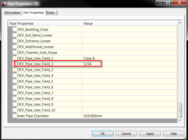
The bedding class must be specified in the Pipe User Field 1.
User fields can be modified in the Pipe Properties window or they can be modified globally with the Edit User Fields command in the Pipe Design panel:
Specify the User Defined Field and Value:
The profile view name is taken from the horizontal alignment name:
The template contains two structure table styles and one pipe table style:
-
Proposed Main Sewer Particulars is a structure table.

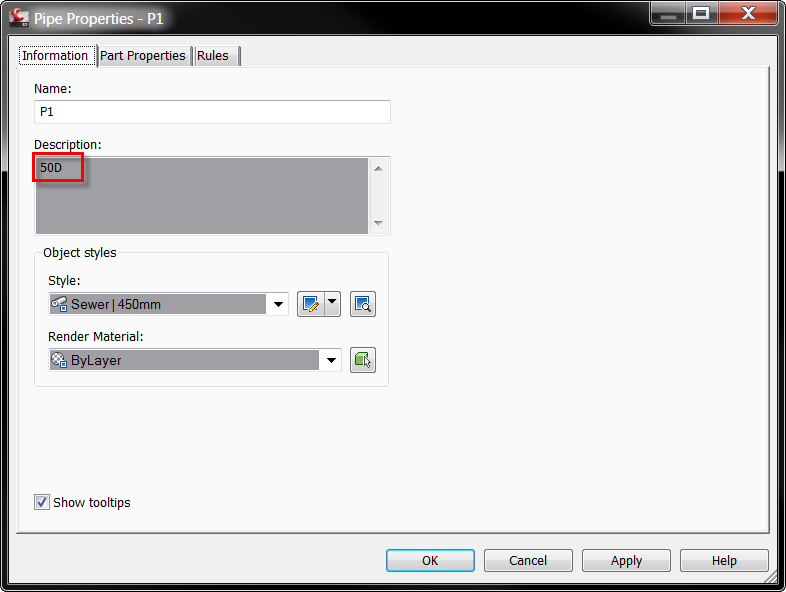
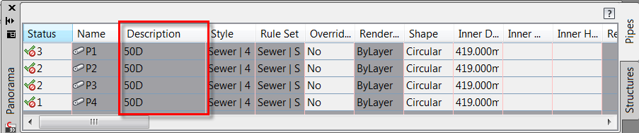
The Downstream Pipe Class data is taken from the pipe description which can be changed in the Pipe Properties window or in the panorama window (faster option for multiple pipes):
-
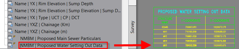
The Proposed Water Setting Out Data is a structure table for water networks. It is mentioned here just for comprehensiveness:
-
The Proposed Sewer Erf Connection Setting Out Details is a pipe table:

Column headings:

The first column Erf. No. is taken from the Pipe User Field 2: